Feed Manager Hired Hand Manufacturing, Inc. 1733 County Road 68 PO Box 99 Bremen, Alabama 35033 Manual No.
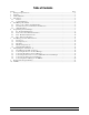
Table of Contents Section Title Page 1. Ratings and Specifications.............................................................................................................................3 2. Warnings .......................................................................................................................................................3 3. Limited Warranty ......................................................................................................................................
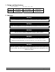
1. Ratings and Specifications • Temperature Range…………..32°F - 122°F (0°C – 50°C) HHI Part Number Description Power Supply Temperature 6607-8036 Feed Manager 120/230 VAC 50/60 Hz 32° F thru 122°F (0° C thru +50° C) 2. Warnings Warning! Only a certified electrician should install or maintain electrical connections. Warning! Proper safety equipment must be used during installation of Feed Level Sensor. Warning! Do not install or maintain equipment during a lightning storm.
3. Limited Warranty All products are warranted to be free from defects in material and workmanship for a period of one year from the date of purchase if installed and used in strict accordance with the installation instructions. Liability is limited to the sale price of any products proved to be defective or, at manufacturers’ option, to the replacement of such products upon their return.
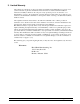
4. Introduction The Feed Manager is the latest technology in the Hired-Hand controller family. This technology adds the stand-alone controller capability for monitoring feed levels in bins and run times of feed augers. One Feed Manager controller can monitor up to four feed bins and two feed augers from two buildings. Beyond monitoring, it also adds alarm features to help detect feed spills or prevent running out of feed.
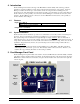
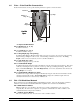
5.1 Mode, + and - Buttons and Main Display Mode Button – The Mode button is used to select a controller function. Press the Mode button to toggle between specific feed bins and functions. The Mode Indicators light when a function is selected and the associated data is displayed in the Main Display. By pressing and holding the Mode button for at least 5 seconds, the Feed Manager can be placed in the Program Mode as discussed in Section 6 of this manual.
5.3 Alarm Indications Normal Operation – During normal operation with no alarms present and no specific feed bin or specific operation selected, the following indications will be shown: • The Main Display will continuously show the active feed bin numbers. • The Feed Level Indicators for the active bins will be displaying the feed levels. • The Auger Fill Indicators will either be solid-ON when the auger motor is running or solidOFF when the auger motor is not running.
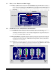
“Err” representing that an Error/Alarm condition exists. As soon as the alarm condition clears, the Auger Fill Indicator and Main Display return to normal operation. NOTE: A Current Sensor (6407-6070 ordered separately) or Sens-O-Matic III feed controller (66062000 for a 120vac model or 6606-2100 for a 230vac model ordered separately) is required for this function. 6. Programming the Feed Manager This section introduces the Feed Manager programming software.
P2 – Feed Sensors Activated This general parameter is used to turn additional feed bins ON (press the ‘+’ button) or OFF (press the ‘-‘ button). For example, if you only have two feed bin sensors connected to this control, you can disable bins #3 and #4 displays by setting this to “1 2 - -“. P3 – Feed Sensor Type Program selection not available at this time. Dead Zone P4 – Feed Sensor Dead Zone (ft, m) Dead Zone refers to the area that the sensor is hanging into the feed bin.
6.2 P10.x – P19.x Feed Bin Characteristics Feed bin characteristics are the specific feed bin parameters required to monitor feed bins: Dead Zone Top Angle Number of Rings Bin Height Ring Height Feed Bin Specs Diameter “x” Represents Bin Number P10.x – Diameter (6’, 7’, 9’, 12’) Feed Bin #x diameter. P11.x – # of Rings (1, 2, 3, 4, 5) Feed Bin #x number of rings. P12.x – Ring Height (Typ. 2.65’ [0.
P42 – Controller Setup This is not settable by the user. It is a unique number that allows the network software (Farm Manager) to recognize the type of controller. 6.4 PS1 – PS9 Sensor Readings The Feed Manager will accommodate up to four Feed Level Sensors. The sensor reading will display for PSx where x is the sensor number. This is a precise reading used mainly for troubleshooting purposes. NOTE: As the feed level decreases, the sensor reading number will increase (Range = 0 thru 255).
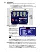
7.1 Feed Level Feed Level When the Feed Level indicator is ON, the Main Display will show the amount of feed remaining in the specific feed bin. The Feed Level is shown in number of feet or meters from the feed bin’s boot. The unit of measure (Feet or Meters) can be set in the Program P1 setting (Refer to Section 6.1). View the Feed Level by pressing the specific required Bin Selection Button (1, 2, 3, or 4). The specific Feed Bin Level Indicators will repeatedly flash to indicate the selected feed bin.
7.4 Min. Feed Capacity (%) The Min. Feed Capacity feature Min Feed Capacity monitors the amount feed in the feed bins and will activate the Auxiliary Alarm output if the feed decreases below the selected amount of minimum feed. When the feed level decreases below the Min. Feed Capacity (%) percentage, the specific Feed Bin Level Indicators will immediately start flashing. To view or change the Min.
For example, if 15 is selected, the Auxiliary Alarm will activate if the run time exceeds 15 minutes. To increase or decrease the Max. Fill Time minutes, press the Plus + or Minus - button until the desired value is shown in the Main Display. To turn the Max. Fill Time function OFF for both feed auger motors, repeatedly press the Minus - button until OFF is shown in the Main Display. To view or change the Max. Fill Time setting, press the Mode Select button repeatedly until the Max.
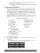
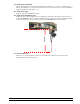
8. Wiring Diagrams, Schematics, etc. The following diagrams describe the Feed Manager circuit board connections and how the Feed manager is connected to external equipment. Processor Part No. 4801-2994 Rev 10-05 Option Board Connection 1.2 Amp Slo-Blow Fuse – F1 Net Term Jumper Auxiliary Alarm Feed Bin # 4 Feed Bin # 3 Feed Bin # 2 Feed Bin # 1 Auger #2 Auger #1 HH.Net AC Power Connector Feed Manager Circuit Board Layout Voltage Selector Switch 8.
8.2 Connecting AC Power to the Feed Manager Feed Manager Inset B Inset A WARNING: Ensure that the Voltage Selector Switch shown in Inset B is set according to the AC Supply voltage. Equipment damage will occur if this switch is not set correctly. Inset B OR Part No.
8.3 Connecting Feed Bins to the Feed Manager Feed Manager Inset A Feed Level Sensor (Mounted on top of the feed bin) Part No.
8.4 Connecting a Current Sensor or Sens-O-Matic III to the Feed Manager Feed Manager Inset A Breaker Box Feed Auger Motor L2 L1 Run Sensor Sens-O-Matic III Circuit Board Run Sensor Connections (Exploded View) Red Black OR Current Sensor Auger #1 Inset A NOTE: Either a Current Sensor or a Sens-O-Matic III may be used to monitor the Feed Auger Motor Runtime. Part No.
8.5 Connecting an Alarm to the Feed Manager Feed Manager Inset A For Parallel Alarm Connection NOTE: For Series Alarm Connection The internal wiring shows the condition of the relay during normal conditions (no alarm present). During an alarm condition, the contact positions will be reversed. Internal Circuit Board Auxiliary Alarm Relay Part No.
8.6 Connecting the Feed Manager to the HH.Net Feed Manager Inset A Inset B Part No.
9.
10. NOTES Part No.