
Owner manual

Part No. 4801-5331 Rev 2-08 Evolution 1200 9 of 64
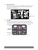
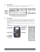
5.5 Status Display
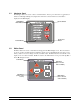
The following is an example of Main Display screen displaying the standard Target Conditions status
screen. The Main Display screen displays both status and programming screens.
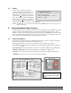
5.6 Stage Switch
The stage LED indicator lights when a stage is active. The stage switch is used to select Auto operation,
On, or Off. If switch is in Auto position, the stage operation is controlled by the controller. That is, the
stage may turn on and off according to settings selected from the Main Display screen. If switch is in the
On position, a stage is On continuously. If switch is in the Off position, a stage is Off with the exception
of Back-Up conditions.
The white space is used to affix a Stage Description label indicating stage function (i.e. brooder, fan, light,
cool, etc.).
NOTE: Stages 1 thru 8 are marked on the front panel. For optional Variable Stages 7 & 8, use stick-on
V1/V2 label placed over stages 7 & 8 numbers.
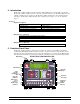
Stage numbe
r
(Use V1-
V
2 label ove
r
Stages 7 & 8 if Stages 7
& 8 are used fo
r
Variable Output).
AUTO, OFF, ON
Switch positions
Stick Stage
Description label onto
white area or use fo
r
LED Indicator (lights
when stage is ON)
Stage Description labels
are provided to affix to
white area of stage
control. Stage
Description labels are
shown at right.
The Scroll Symbol is a
flashing down arrow (") that
indicates more text outside o
f
display screen. Use up/down
editor arrow keys bc to
scroll text.
The Link Symbol () is a right
pointing arrow and indicates a
link to another display screen.
To change
parameter:
Select parameter
using editor
arrow keys. Use
+ and - keys to
change value.
"
(1)Target Temp = 77.5° (2)Ramping: On
(3)Target Press = 0.04 wc (4)Ramping: Off
(5)Tunnel Press = 0.00 wc
(6)Target Humidity < 60%
(7)Light Schedule
(8)Feed Schedule
7
7.5°
NOTE: If Optimum Mode is turned On, the Target Conditions screen
will have differences from the standard screen shown above.