
Owner manual

Part No. 4801-5331 Rev 2-08 Evolution 1200 40 of 64
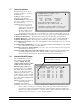
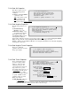
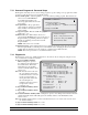
(7) Feed Level Sensor – Settings for setting the maximum range and calibration of the feed level sensor.
(8) Maximum Range - Total sensing range of the sensor.
(9) Dead Zone - Distance from the top of the feed bin to the bottom of the sensor.
(10) GPAD12 thru GPAD15 – For HHI Service Technician Use ONLY.
General Purpose A/D Readings:
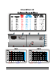
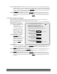
As shown on the Diagnostics screen in Section 7.14, there is a section with four displays labeled
GPAD12, GPAD13, GPAD14, and GPAD15. These values represent the data being received
from the I/O Expansion Board, if equipped. These values will be used to troubleshoot your
controller by a qualified service technician in the case that a problem occurs with your I/O
Expansion board. The following tables give you an idea of the range of values and what they
represent.
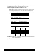
GPAD12 & GPAD13 -- Feed Level Sensor Inputs
Range Status Cause
0-24 Bin is full
Feed is on or above proximity
rod.
25-57 Loss of Echo
Bin may be empty or a sensor
error
58-239 Sensing Feed
Value should be based on level
of feed with 58 being
approximately full.
240-255 Error
Could represent empty but
probably a defective sensor.
GPAD12 = Bin 1
GPAD13 = Bin 2
GPAD14 -- Current Sensors for Auger 1, Auger 2, Belt 1
Motor Status
Range Auger 1 Auger 2 Belt 1
0-115 On On On
116-124 Off On On
125-136 On Off On
137-151 Off Off On
152-169 On On Off
170-194 Off On Off
195-224 On Off Off
225-255 Off Off Off
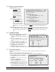
(11) Soft Resets - For HHI Use Only. Indicates that the control is sensing environmental problems which
can cause controller malfunctions.
(12) Voltage Resets - For HHI Use Only.
(13) Hard Resets - For HHI Use Only.