Evolution 1200 Environmental Controller Hired Hand Manufacturing, Inc. 1733 County Road 68 PO Box 99 Bremen, Alabama 35033 Part No.
Table of Contents Section Title Page 1. Ratings and Specifications ............................................................................................................................4 2. Warnings .......................................................................................................................................................4 3. Limited Warranty ......................................................................................................................................
7.10 Stage Properties ....................................................................................................................................34 7.10.1 Heat Properties .............................................................................................................................34 7.10.2 Cool Stir Properties ......................................................................................................................35 7.10.3 Cool Negative Properties........................
1.
3. Limited Warranty All products are warranted to be free from defects in material and workmanship for a period of one year from the date of purchase if installed and used in strict accordance with the installation instructions. Liability is limited to the sale price of any products proved to be defective or, at manufacturers’ option, to the replacement of such products upon their return.
4. Introduction The Evolution 1200 Controller is the latest member of Hired-Hand's new environmental controller line. The Evolution 1200 Controller has most of the same operational features as the Evolution 3000 except the 1200 has a smaller size and overall cost. The Evolution 1200 Controller has 8 stages standard plus two inlet stages. The Evolution 1200 Controller can be expanded up to 64 stages. (i.e. 16, 32, 48 and 64 stages).
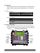
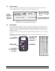
5.1 Navigator Panel The Navigator buttons are used to select a controller function. Press up or down button to toggle between functions. LED (light emitting diode) lights when a function is selected and the associated data is displayed in the Main Display. Light Emitting Diode Indicator Up Select Button Down Select Button Function Modes 5.2 Editor Panel The Editor buttons are used to select functions that appear in the Main Display screen.
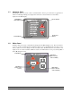
5.3 Main Display Contrast The main display contrast can be adjusted to adapt to various lighting conditions. The Contrast Control is located on the opposite side of the front panel. Use the Contrast Control potentiometer and a small flathead screw-driver to manually darken or lighten the screen. Turn clockwise to darken the display; Counter-clockwise to lighten the display. CAUTION: DO NOT CONTACT OTHER COMPONENTS OR WIRES. Contrast Control 5.
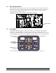
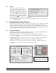
5.5 Status Display The following is an example of Main Display screen displaying the standard Target Conditions status screen. The Main Display screen displays both status and programming screens. To change parameter: Select parameter using editor arrow keys. Use + and - keys to change value. (1)Target (3)Target (5)Tunnel (6)Target Temp = Press = Press = Humidity 77.5° 77.5° 0.04 wc 0.
5.7 Locks A lock feature is included for additional security to the Evolution 1200 settings. This ** PASSWORD PROTECTED ** You must enter the current controller feature locks the Program Setup screens to Password to continue. prevent changes. Locked screens are noted by Press the ENTER button to proceed. a lock symbol ( ) in the upper right of the screen. The Target Conditions and Minimum Password: XXXX Vent screens are not lockable.
VENT MODE Minimum Natural Power Transition Tunnel Definition Heat stages or timer fans operating. None of the negative stages are on because of temperature. The main curtains are open. The curtains are up and there are negative fans on because of temperature. The control is transitioning into tunnel ventilation from either power or natural ventilation. The control is making the adjustments needed to go into tunnel. The tunnel signal has been activated and the system has entered into tunnel.
6.2 Target Conditions The current target environmental conditions of the building are shown below. The specific Target Conditions screen features and setting options will depend on whether Optimum Mode is ON or OFF. Examples and details for both the Standard screen and Optimum screen are shown in the following two subsections. 6.2.1 Target Conditions - Standard Screen With Optimum Mode OFF (1)Target (3)Target (5)Tunnel (6)Target Temp = Press = Press = Humidity 77.5° 0.04 wc 0.
6.2.2 Target Conditions - Optimum Screen With Optimum Mode ON The target conditions screen shown below represents the display and options when the Optimum Mode is turned On. Refer to Section 7.1 for turning the Optimum Mode On or Off and Section 7.6.2 for the Optimum Mode Growout Curve. Optimum Settings (1)Target Temp = 77.5° (3)Optimum Run%: 10% (5)Target Press = 0.04 wc (7)Vent Level: --6-4--(9)Light Schedule Adjustments (2)Adjust = +0.0° (4)Adjust = +00% (6)Tunnel = 0.
6.3 Minimum Vent The Minimum Vent status screen display: (1) MINIMUM TIMERS: (2)Cycle = 5 m ( 300s) (3)Min1 % = 40% ( 215s) (4)Min2 % = 20% ( 108s) (5)Var % = 20% ( 108s) (9)VARIABLE (10)Sensors (11)Max Run (13)Min Run TIMER: = Outside % = 65% % = 20% (15)COOL TIMER: (16)Max Run % = 100% (18)Min Run % = 55% " (6)VARIABLE SPEED: (7)V1 Minimum % = 50%(55%) (8)V2 Minimum % = 40%(100%) NOTE: Run Time in seconds (12)Max Temp = 85.0° (14)Min Temp = 70.
(17) Cycle - Cycle Time in Minutes. Cool timer is also allowed a different timer cycle if needed. This will be used for foggers or cool cell systems. 6.4 (18) Min Run - The Cool Timer Minimum Run Time percentage. Stage Conditions When the Stage Conditions screen is selected by using the Navigator Select arrows, the following menu screen is shown. Use the up and down arrows in the Editor to view the desired information.
6.4.2 Onboard Stages The Onboard On/Off stages 1 thru 6 are used for devices that do not need a variable speed capability. Stages 7 & 8 are user selectable to be either Variable Speed Fan Outputs or regular On/Off Stages. Refer to Section 8.2 for Stages 7 & 8 mode selection diagrams and details. This On/Off Stages screen shows you how onboard stages 1 thru 8 and also the variable stages V1 & V2 are set. For expansion stages, refer to Sections 6.9 and 7.8.
(5) ON – The temperature at which the stage operates. (6) OFF and (7) TIME – This column indicates if the machine is fully closed. When the machine is on the closed auxiliary switch, this column will display “Yes”. 6.4.4 Variable Stages The Variable stages are used to control devices (i.e. fans & lights) with a variable capability. The same V1 & V2 settings shown in this screen are also shown in the top portion of the Onboard On/Off Stages screen. (1)# . V1 . . . V2 . . (2)STATUS . 50% . . . 75% . .
NOTE: The High and Low temperature readings are taken from the Sensors for Display in "Sensor Setup" of the Program Setup Screen. 6.5.2 Humidity Sensor This screen shows the highest room humidity " for each day for up to 99 days. The last day (1)DAY (2)High Humidity 21 70%-12:34p reported will appear at the top of the list. The 20 70%-12:34p list can contain data up to 99 days. After . . . displaying 99 days, oldest data will be . . . 1 70%-12:34p deleted. (1) Day – The specific day in the growout period.
6.5.5 Feed History This screen shows the estimated daily (1)Day (2)Usage (3)Auger1 (4)Auger2 amount of feed used and the total time (5)Status On On 41 2100 lb 4:10 9:10 that the feed line motors have been 40 2000 lb 3:00 8:00 running. . . . . (1) Day – The specific day in the 35 1500 lb 3:00 8:00 growout period. Values = . . . . . . . . 1 to 99 days. 24 1000 lb 1:30 6:30 (2) Usage – The amount of feed used . . . . from Bin #1 and Bin #2 . . . . 1 150 lb 1:10 6:10 combined for each day of growout.
6.5.8 Alarm Log This screen shows the list of the past 20 alarms and status information starting with the most recent occurrence. (1) Alarm Description – ** Alarm Log ** " 1 (1)Tunnel Vent (2)Corrected @ (3)2/ 5 (4)1:26p The alarm 2 Low Press Failure @ 2/ 5 1:09p problem area.
6.7 Alarm Status The ALARM column lists the elements and sensors that are available. For the High and Low temperatures and High and Low pressure, the Cycle Pressure the current Alarm Limits are shown. For all entries the STATUS and the LAST REPORTED alarm are indicated. To change the ALARM LIMIT use the Editor arrows to highlight the desired entry and the Plus (+) and Minus (-) buttons to increase or decrease the desired limit. Proceed to Detail Screens TEMPERATURE (1)High Temp (2)Low Temp LIMIT 85.
(7) Low Rate - Low water usage rate. Alarm if units per hour drop below. One or two water meters (#1 or #2) can be monitored. NOTE: Low Alarm is disabled when lights are off. (8) Auger Run1 - Alarm if continuous runtime of feed line #1 exceeds selected time limit. (9) Auger Run2 - Alarm if continuous runtime of feed line #2 exceed selected time limit. (10) Tunnel Vent - The Tunnel alarm will send a signal if for some reason the controller is unable to enter tunnel. See Section 6.7.3.
(6) Cause - Displays the reading of the low temperature that caused the alarm. Possible Reasons for Low Temperature False Alarm Conditions: • If the same sensor causes multiple alarms, check the location of the sensor and wiring for possible damage. Also insure that the limit is properly set for the target and room temperature. 6.7.3 Tunnel Vent Alarm Details The Tunnel Alarm Details shows the settings for the alarm, the last time the alarm was sounded and the cause of the alarm.
6.8 Network Status The Network Status shows the installed Evolution Stages, the Back-Up and the Heat Zone. The ENABLED indicator shows if the stage is enabled and the STATUS indicates OK or Failed. (1) Modules – The Evolution modules that can be installed will appear here. EV I/O - This is the back board of the Evolution 1200.
7. Setting Programming Functions This section discusses the programming screens for the Evolution 1200. 7.1 General Settings (1) (2) (3) (4) 7.2 The General Settings contains parameters that usually only need to be set once when the system is installed. To change any of these parameters, use the EDITOR arrows to navigate through the list and the plus (+) and minus (-) buttons to increase or decrease the values. Software Version – The software version currently in use. HHNET Address - HH.
(5) Value – Current temperature reading. (6) Adjusted – This will indicate if the sensor temperature has been calibrated and the amount of recalibration. 7.3 Feed Level Sensors The Feed Level Module Setup screen sets the parameters required to monitor feed ** Feed Level Module Setup ** bins. (1)Bin 1: (1) Bin 1 - These settings provide the feed (2)Diameter = 6 ft (3)Cap Angle = 30° level sensor at Bin #1 with necessary (4)# of Rings = 1 (5)Ring Height = 2.67ft (6)Feed wt: 00 lb (7)Bin ht: 9.
(5) Reaction Delay – The amount of time delay before the vent machine operates. (6) Pressure Differential - Number from target to start opening and closing vents. Example: With Target 0.07 and Differential 0.02, the vents open when the pressure is above 0.08; The vents will close when the pressure is below 0.06. (7) Pressure Ramping – Select On or Off to enable or disable pressure ramping. (8 & 9) Target Press. @ High Temp - The target pressure when the outside temperature is at the high temperature limit.
(9) Sensors – Identify the sensors used by the controller. This will be the sensor that the curtain machine will operate from. Active sensors will be indicated by a number starting with #1 from right to left. Inactive sensors will be indicated by a - or hyphen. When "outside-" is displayed, outside sensor is active. To use sensors 1,2 and 3, "-----321" should be displayed. See (7). (10) Mode – Natural (NAT) or Natural Tunnel (N&T). Sets unit 2 to Tunnel Inlet also.
NOTE: The graph below shows an example of how the EV would adjust the target temperature based on the growout day. 7.6.2 Growout Curve With Optimum Mode ON If Optimum Mode is enabled, the grow-out curve screen will expand to the following form. In addition to the Target Temperature Curve, the table expands to include a Heat Adjustment (HEAT AJST), a Tunnel Adjustment (TUNNEL AJST), a maximum number of tunnel fans, a minimum runtime percentage, and a minimum vent level.
(5) Target Temperature Differential – When enabled, this feature will adjust the target temperature either higher or lower by the selected number of degrees during the selected time of day. a. Enabled – Select Yes to enable or No to TARGET TEMPERATURE DIFFERENTIAL disable Target Temperature (a)Enabled = Yes (b)Target Adjust = +5.0° Differential. (c)Adjust Between 11:00a and 1:00p b. Target Adjust – The desired degrees above or below the Target Temperature. c.
EXAMPLE OF Tunnel Adjust Heat Adjust Part No.
7.7 Tunnel Ventilation The Tunnel Setup screen sets the **TUNNEL SETUP**((1)Target = 75°) parameters necessary to operate in the Tunnel mode. (2)Tunnel Enabled = ON (1) Target – Displays the target temperature of the building. Tunnel (3)Sensors Temperature On (4)---54321 (5)85.0° (2) Tunnel Enabled – Select either Off (6)-----3-1 (7)80.0° Yes or No to enable or disable going into the Tunnel mode.
(4) Mode – This mode column will indicate how the stage is Programmed to operate. (OFF) Disables stage from operating during automatic operation. (Heat) Heat Mode: This method of heating only operates when the curtains are in the closed position and the operating sensor is below the on temperature. (CSTIR) Cool Stir Mode: This mode setting allows the cool stage to run whether the main curtain is open or closed.
(5) MaxON - This MaxON column will indicate the current setting for the Maximum onpoint temperature of the stage. Set this to the temperature you would like for the stage to reach the desired maximum speed. (6) MinON - This MinON column will indicate the current setting for the Minimum onpoint temperature of the stage. Set this to the temperature you would like for the stage to start running its minimum speed setting. Minimum speed setting is set at the Minimum Vent screen of the Navigator.
7.10.2 Cool Stir Properties This allows stir fans to act as mixing fans during tunnel ventilation. (1) Allow to operate in Tunnel – Select Yes or No. YES = The stir fans operate in any ventilation mode. NO = The stir fans will NOT operate during tunnel ventilation. ** Cool Stir Properties ** These stages typically operate fans That are used to stir the air inside The building. They operate in all Ventilation modes. (1)Allow to operate in Tunnel = No 7.10.
(2) Growout Day Override – During the first days of the growout period, especially during brooding, the Evolution 1200 can be set to only allow the cool tunnel stages to operate after a specified number of days in the growout period. When set to Only While, the Growout Day Override will allow the stages to operate only while the growout day is greater than the day you set. Otherwise when set to Always, the day of growout will not affect the stages.
7.10.7 Natural Ventilation Properties (1) Time Override - When set to Only While, the Time ** Natural Ventilation Properties ** Override will allow the The Natural Ventilation Stages typically Natural Curtain Stages to operate sidewalls. The following are some additional properties: open while the time is between the times you set.
(5) (6) (7) (8) 7.12 Every Day – No days skipped. Odd Days Only – Runs the feed cycles ONLY on the ODD growout days (1, 3, 5, 7, etc.). Even Days Only – Runs the feed cycles ONLY on the EVEN growout days (2, 4, 6, 8, etc.). Selected Days – Runs the feed cycles only on the selected days chosen in item 5. Choose Days – Select the specific days for operation. Used only when Days In Operation item 4 is set to “Selected Days”. Cycle – This identifies the feed cycle.
7.13 Seasonal Programs & Password Setup The Programs & Security screen is used to change programs, copy the settings of one program into another program or set the password to access applicable screens. (1) Seasonal Programs – Select Program 0, 1, or 2 for the current operating program. This selection can also be used to COPY FROM the **PROGRAMS & SECURITY** Seasonal Program number to the selected program number shown in the (1)Seasonal Program = 1 item 3 below.
(7) Feed Level Sensor – Settings for setting the maximum range and calibration of the feed level sensor. (8) Maximum Range - Total sensing range of the sensor. (9) Dead Zone - Distance from the top of the feed bin to the bottom of the sensor. (10) GPAD12 thru GPAD15 – For HHI Service Technician Use ONLY. General Purpose A/D Readings: As shown on the Diagnostics screen in Section 7.14, there is a section with four displays labeled GPAD12, GPAD13, GPAD14, and GPAD15.
8. Wiring Diagrams 8.1 Inside the Evolution 1200 Enclosure LOW VOLTAGE WIRES PCB 186 HIGH VOLTAGE WIRES HIGH VOLTAGE Electrical Shield (Removed for Clarity) PCB 188-1 Stage 7&8 or Variable 1&2 Output Connections (Refer to Section 8.2). Bottom View of Enclosure PCB 188-2 Stages 1-6 Stage Relays & Output Connections PCB 188-3 Ventilation Inlets Relays & Connections or Natural Unit #1 (Refer to Section 8.2).
8.2 Setting Stage & Inlet Option Switches on EV1200 PCB 186 Board Stages 7 & 8 Output Terminals PCB 186 Option Switches UP NOTES PT Unit #2: Switch Down = Power Ventilation Switch Up = Natural Ventilation Stage number (Use V1-V2 label over Stages 7 & 8 if Stages 7 & 8 are used for Variable Output).
8.3 Connecting Temperature Sensor to Evolution 1200 PCB 186 Inset A WARNING! LOW VOLTAGE! Keep Separate From High Voltage Wires! Inset A NOTE: Other sensors are connected similarly. Warning! Tape Shields To Prevent Bare Wires From Touching! Part No.
8.4 Connecting Remote Static Pressure Monitor to Evolution 1200 PCB 186 WARNING! Inset A Blk Red Inset A Wht LOW VOLTAGE! Keep Separate From High Voltage Wires! COM OUT EXC Remote Static Pressure Monitor 8.5 Connecting Humidity Sensor to Evolution 1200 PCB 186 WARNING! LOW VOLTAGE! Keep Separate From High Voltage Wires! Humidity Sensor Inset A Inset A Part No.
8.6 Connecting PC Network to Evolution 1200 PCB 186 Inset A WARNING! LOW VOLTAGE! Keep Separate From High Voltage Wires! Inset A Twisted Pair Cable 8.7 Connecting Alarm Device to Evolution 1200 Inset A PCB 186 Switch Positions WARNING! LOW VOLTAGE! Keep Separate From High Voltage Wires! Inset A N.C. IN N.C. OUT N.O. IN N.O.
8.8 Connecting Water Meter to Evolution 1200 Inset A PCB 186 Inset A Sig. GND R B G Water Water Meter #1 ABB 8 7 Inset B 9 0 1 6 5 4 2 3 WARNING! LOW VOLTAGE! Keep Separate From High Voltage Wires! Inset B Sig. GND R B G Water Water Meter #2 ABB 8 7 9 0 1 6 5 4 2 3 Part No.
8.9 Connecting the PowerTrak to the Evolution 1200 PCB 188 WARNING! Keep High Voltage (Or AC) Separate From Low Voltage Wires! Inset B Inset A PCB – 188 Power Ventilation Inset B AUX SWITCH CONTROLLER HOT Inset A Unit #1 Vents NEUT. GND. CLOSE IN OPEN IN HOT OUT LOWER COM UPPER PowerTrak AC IN Com Open Close NOTE: If curtain is setup to pull curtain up to open, then reverse wires connected to "OPEN" and "CLOSE" terminals. NOTE: Only 1 Power Trak can be connected to each Power Trak outlet.
Connecting the PowerTrak and EV S3 to the Evolution 1200 8.10 PowerTrak ! WARNING! • Keep High Voltage (Or AC) Separate From Low Voltage Wires! • Do not perform modifications or wiring with voltage applied! Evolution S3 Circuit Board Tunnel Override Inset B Vent Override Inset A NOTE: If connecting the S3 to a relay box instead of PowerTrak, Cut and discard the four components shown. Inset B Vent Override CONTROLLER HOT NEUT. GND.
8.11 Connecting the PowerTrak Power Auxiliary Switches to Evolution 1200 PCB 186 Inset A Inset B Inset C WARNING! LOW VOLTAGE! Keep Separate From High Voltage Wires! Inset C AUX SWITCH CONTROLLER AC IN HOT NEUT. GND. CLOSE IN OPEN IN HOT OUT LOWER COM UPPER PowerTrak Inset A Tunnel Auxiliary Input Inset B Vent Auxiliary Input Open Close Com AUX AUX Tunnel Aux. Input Open Close AUX Com AUX Vent Aux. Input See Note below NOTE: Vent auxiliary connects the same as tunnel auxiliary.
8.12 Connecting PowerTrak Natural Auxiliary Switches to Evolution 1200 PCB 186 Inset A WARNING! Inset B LOW VOLTAGE! Keep Separate From High Voltage Wires! Inset A Natural Auxiliary Input Inset B AUX SWITCH CONTROLLER HOT NEUT. GND. CLOSE IN OPEN IN HOT OUT LOWER COM UPPER PowerTrak AC IN Close Close Aux. Com. Aux. Com. Auxiliary Inputs NOTE: If curtain is setup to pull curtain up to open, then reverse wires connected to 'Upper' and 'Lower' terminals. Part No.
Part No. 4801-5331 Rev 2-08 Inset A (AC Input on PCB 186) Evolution 1200 Keep High Voltage (Or AC) Separate From Low Voltage Wires! WARNING! Evolution 1200 Control WARNING: Ensure that the Voltage Selector Switch shown in Inset B is set according to the AC Supply voltage. Equipment damage will occur if this switch is not set correctly. Controllers are shipped from HHI set to 240V.
8.14 Evolution 1200 Power Connection Connecting Power from Breaker to a Heat Stage And a Cool Stage in the Evolution 1200 PCB188-1 PCB188-2 Evolution 1200 Terminal blocks for stage connections NOTE: Example above shows how to wire stages to heating & cooling equipment. Stage numbers are shown on the PCB above terminal blocks. WARNING! Keep High Voltage (Or AC) Separate From Low Voltage Wires! Part No.
8.15 Connecting Local Network & Backup to the Evolution 1200 WARNING! LOW VOLTAGE! Keep Low Voltage Wires Separate From High Voltage Wires Local Network PCB 186 PCB188-1 J18 TR101 J31 J22 N.C. N.C. N.O. N.O. IN OUT IN OUT J17 Sig. J10 J14 +12V Sig. J11 +12V Sig. Humidity Sensor Static Pressure J12 J9 J24 J39 +12V #1 #2 #3 #4 0-10Vdc 4-20mA General Purpose Analog Inputs J15 J16 +12V Sig.
9. Temperature vs. Sensor Resistance Table The following chart gives the resistance when measured between the white and black sensor wires at a given temperature. To check a sensor, first know the temperature in the area, then use a multi-meter to check the resistance. Resistencia Kohms 32.654 32.158 31.671 31.191 30.72 30.257 29.802 29.355 28.915 28.482 28.057 27.777 27.363 26.957 26.557 26.164 25.777 25.523 25.147 24.777 24.413 24.055 23.82 23.472 23.13 22.793 22.572 22.244 21.922 21.71 21.397 21.088 20.
10.
Circuit Boards 6407-1585 6407-1589 6407-1591 6407-1587 6407-6011 6407-0621 /PCB186 EV1200 BackBoard w/QA /PCB188-2 EV1200 Stg 1-5 w/QA /PCB188-3 EV1200 PT w/QA /PCB188-1 EV1200 Stg 7-8 w/QA EV Display Assy.
Manuals 4801-5331 4801-5328 4801-5307 4801-5308 4801-5309 4801-5310 4801-5315 4801-3001 4801-2997 4801-2998 4801-2995 4801-2996 4801-5152 MANUAL EV1200 MANUAL Temp Sens Junction Box MANUAL EVOLUTION 3000 MANUAL Evolution Ventilation.
Notes Part No.
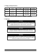
Hired-Hand, Inc. Poultry House Layout and Specification 1. House Specification Building Size Name: Vents Legend Stage Equipment 1 2 3 4 5 6 7 8 9 10 11 12 13 14 15 16 17 18 19 20 21 22 23 24 25 26 27 28 29 30 31 32 Sensors S Main B Backup A Alarm Equipment O Brooders F Fans H Heaters T Tunnel Machine V Vent Machine * Indicates distance from end wall on equipment * Mark fans with size and number Inlet Size HIRED-HAND, INC.
Hired-Hand, Inc. Poultry House Layout and Specification 2. Stage Programming Target _____ Stage Sensors On Point Off Point Mode Timers 1. 2. 3. 4. 5. 6. 7. 8. 9. 10. 11. 12. 13. 14. 15. 16. 17. 18. 19. 20. 21. 22. 23. 24. 25. 26. 27. 28. 29. 30. 31. 32. Modes: Heat, Cool Stir, Negative, Negative Tunnel, Tunnel, Feed, Lights Timers: Minimum 1, Minimum 2, Variable, Cool Part No.
Hired-Hand, Inc. Poultry House Layout and Specification 3. Temperature Curve Target Growout Day 4. Static Pressure Settings Vent Inlet Static Pressure _____ Pressure Ramping off of Outside Temperature Pressure _____ at _____ High Temperature. Pressure _____ at _____ Low Temperature. Vent Delay _____ (seconds) Vent Anticipation _____ (seconds) 5. Minimum Vent Timer Cycle _____ (minutes) Day Timer % Stages 6.
Hired-Hand, Inc. Poultry House Layout and Specification 7. Lighting Program Day 8. Day On Time Run Time (hours: minutes) Intensity Schedule/ Ramp Feed Program On Time Run Time (hours: minutes) Part No.
Hired-Hand, Inc. Poultry House Layout and Specification 9. Back-up Specifications Back-Up Stages Equipment (Stage Number) Other Requirements: Heat Cool 1 Cool 2 Cool 3 10. Alarm Specifications Alarm Settings Other Requirements: High Temperature Low Temperature Cycle Pressure High Pressure Low Pressure (If used in Tunnel) High Water Usage Low Water Usage Part No.
Hired-Hand, Inc. Poultry House Layout and Specification 11. Notes Part No.