
Manual

Manual No. 4801-3001 Rev 7-08 Secondary Sensing System Expansion 32 of 46
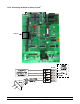
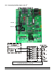
P 1-9 Genera l Para mete rs
P1 = Temperature Units
C = Celsius
P2 = Individual Alarm Temperature Limits
F = Fahrenheit
Yes = Tem
p
erature Limits Set Individuall
y
No = Temperature Limits Set Identical
P3 = Back-U p Timer Per cent age
P4 = Back-Up Stage On Delay
P4 = Back-Up Stage On Delay
P 40-49 Hired-Hand Network
P40 = HH Network Address
NET
P41 = Softw are Ve rsion Numbe r
P42 = Controller Setup
P43 = Local Network Enable
No = Not Connected (Stand-Alone)
Yes = Connected (EV Network)
P 60-69 Alarm Functions
P62 = Cycle Pressure Alarm
ON = Enabled
OFF = Disabled
P63 = Minimum Vent Cycle Time (Minutes)
PS Sensor Ca libr ati on
PS1 = Sensor 1 Calibration
PS2 = Sensor 2 Calibration
PS3 = Sensor 3 Calibration
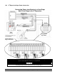
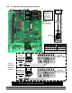
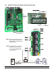
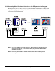
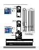
Evolution S
3
16 Stage
Expansion Module
Evolution
Controller
NOTE: Run power cables
including earth ground from
each cabinet to a common
AC junction box. Do NOT
run AC power and ground
between cabinets.
Inset A
(AC Input on S
3
PCB 184)
WARNING!
Keep High Voltage (Or AC) Separate
From Low Voltage Wires!