
Manual

Manual No. 4801-3001 Rev 7-08 Secondary Sensing System Expansion 29 of 46
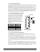
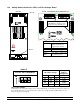
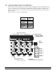
13.3 Connecting Stage Jumpers of S-3 Expansion
Pictured at below is a stage relay board consisting of four stage relays and the associated stage jumper for each
relay. The stage jumpers are labeled COOL 1, COOL 2, COOL 3, and HEAT. Location of the jumper places the
stage in one of these four modes, or if the jumper is NOT inserted, the stage is NOT placed on Back-up. The
jumpers should be placed based on the operation of stage equipment and should be the same as assigned in the
Master Controller.
Jumpers are placed according to the following table:
Stage
Operation
Jumper
Cool Negative COOL 1
Cool Negative
Tunnel Fan
COOL 2
Cool Tunnel Fan COOL 3
Heat Stage HEAT
Stage NOT in
Back-up
No Jumper
installed
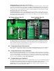
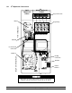
Fail-safe relays
(NOTE: 'Fail-safe'
written on relay board)
Stage harness
connector cables
to terminal block
Stage
Jumpers
HEAT
COOL 1
COOL 2
COOL 3
In
Out
Stage
In
Out
Stage
In
Out
Stage
In
Out
Stage
In
Out
Stage
In
Out
Stage
In
Out
Stage
In
Out
Stage
In
Out
Stage
In
Out
Stage
In
Out
Stage
In
Out
Stage
In
Out
Stage
In
Out
Stage
In
Out
Stage
In
Out
Stage
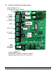
To
PCB 168
To
PCB 168
To
PCB 168
To
PCB 168
Stage Connections
J2
J1
J3
J4
J2
J1
J3
J4
J2
J1
J3
J4
J2
J1
J3
J4
Stage 1
Relay
Stage 2
Relay
Stage 3
Relay
Stage 4
Relay
Stage 5
Relay
Stage 6
Relay
Stage 7
Relay
Stage 8
Relay
Stage 9
Relay
Stage 10
Relay
Stage 11
Relay
Stage 12
Relay
Stage 13
Relay
Stage 14
Relay
Stage 15
Relay
Stage 16
Relay
Fail-safe
WARNING:
Do Not Use Timer Fans On Fail-Safe.