Secondary Sensing System Expansion Owners Manual Hired Hand Mfg., Inc. 1733 Co Rd 68 PO Box 99 Bremen, Alabama 35033 Manual No.
Table of Contents Section Description Page 1. Warnings.........................................................................................................................................................4 2. Limited Warranty............................................................................................................................................4 3. Ratings and Specifications.................................................................................................................
10.6 Temperature Sensors Out of Calibration ..............................................................................................24 10.7 Trouble-Shooting the Auxiliaries .........................................................................................................24 11. Controller Installation and Setup ..............................................................................................................25 11.1 Tools Required ......................................................
1. Warnings Warning! Maximum operating temperature of controller is 50° C (122° F).
3. Ratings and Specifications • • • • • • • 4. Part Number 6607-8038..……. EV-S3-08……8 Stage Outputs Part Number 6607-8039..……. EV-S3-16……16 Stage Outputs Stage Outputs…………………1 HP @ 240 VAC Power Supply…………………240VAC 50/60 Hz Temperature Range…………..32°F - 122°F (0°C – 50°C) Inputs………………………....Three thermistor temperature sensors 32°F – 120°F (0°C - 49°C) Three auxiliary inputs (contact closure) Outputs………………………..One siren (1.
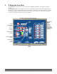
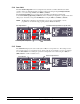
5. S3 Expansion Front Panel The S3 Expansion is divided into two areas. On the left is the Main Control Panel. On the right are the Stage Switches. The S3 Expansion Main Control Panel has six sections on the faceplate. These are the Zone Temperature Section, the Back-Up Section, the Control / Editor Section, the Synchronize / Test Section, the Alarm Status Section, and the Power Switch. The Power Switch is located in the lower-center of the control box as shown below.
5.1 Control / Editor Section Just below the Back-Up Section on the right hand side of the controller is the Control / Editor Section. This section has three buttons: Mode, Plus (+) and Minus (–). The Mode button is used to navigate thru settings and conditions. When the Mode button is momentarily pressed, the green LED Indicators change to the next reading. By pressing and holding the Mode button for at least 5 seconds, the S3 can be placed in the Program Mode as discussed in Section 6 of this manual.
5.1.2 Target The Target mode displays the target temperature used for Zone Alarm Limits and Back-Up Limits. The Zone Alarm Limits and the Back-Up Limits are referenced to the target much like that of a stage on point in a controller. Therefore, once initially set, the user will only adjust the target which will automatically adjust the high and low limits appropriately. The Target temperature can be changed (0.5° increments) using the Plus (+) or Minus (–) buttons.
5.1.4 Low Limit The Low Alarm Temperature is the low temperature at which the controller will indicate an alarm condition. The Low Alarm Temperature is displayed and can be changed using Zone Input Switches (Zones 1, 2, or 3) then using the Plus (+) or Minus (–) buttons. The Low Back-Up Limit is the low temperature at which Heat of the Back-Up will turn ON. See Section 9 (Back-Up Operating Conditions). The Low Back-Up Temperature is displayed and can be changed (1.
5.1.6 History The History Mode displays the High and Low Temperatures for each specific zone, any Back-Up stages which have turned ON, as well as any alarm conditions which have occurred since the last reset. The History Reset function is displayed after pressing the Mode Button once after the Low Temp is displayed. The Zone 1 display will indicate “HIS” and the Zone 2 display will indicate “no” initially.
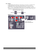
5.2 Alarm System Indicators The Alarm Status LED Display indicates if all Conditions are OK (Green LED) or the specific reason for the alarm condition (Red LED’s). If a red Alarm LED is blinking, the problem may be one of two causes: a. If Conditions OK LED is Green, an Alarm condition exists although the 30 second confirmation timer has not expired. b. If Conditions OK LED is OFF, the alarm condition has been acknowledged (Acknowledge LED will also be ON).
permanent fine-tipped marker. Each auxiliary alarm can be individually enabled or disabled by using the circuit board jumpers. Refer to the Circuit Board Layout in Section 13.4. If the jumper is installed, the AUX 1 or AUX 2 alarm is Disabled; If the jumper is removed, the AUX 1 alarm is Enabled. 5.2.5 Control System Auxiliary The Control System auxiliary input is a special input that should be connected to the main control system.
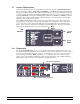
5.3 Back-Up System Indicators The Back-Up System Indicators display the Back-Up operation status and control settings. Refer to Section 9 for additional information. Temperature/Settings Display Back-Up Stages Indicators Ventilation Back-Up Display & Selector Selection Switch Inlet Overrides Indicators 5.3.1 Inlet Overrides Indicators The Inlet Override Indicators indicate if the Back-Up is calling for vent inlets or tunnel inlets to open.
5.4.2 Test/Acknowledge Alarm The Test/Acknowledge Alarm Section has two functions. It allows the user the ability to test the alarm contacts or the ability to silence (acknowledge) an active alarm. Test/ Acknowledge Alarm LED Display 5.5 Test/Acknowledge Alarm Select Buttons Testing Alarm Contacts To test the Alarm contacts, the user can simply press and hold the “Select” button next to the Test/Acknowledge Alarm indicator.
6. Program Mode By pressing and holding the Mode button for at least 5 seconds, the S3 can be placed in the Program Mode as discussed below and on the following pages. Parameter Setting Parameter Number Settings that are usually set up once per grow-out or maybe even just for summer or winter are referred to as program parameters and are accessed by taking the controller to program mode. To get to program mode, press and hold the “Mode” button for five seconds.
P3 – Back-Up Timer Percentage This determines the percentage that COOL 1 will be run in an Emergency condition for minimum ventilation. (10% to 100%). The timer is a five minute timer. A new timer percentage curve feature (added in version V0.09 and later software) automatically changes the timer percentage based on the Target Temperature. The data and table below shows an example: The table and graph above is representative of the curve.
6.2 PC Compatible Hired-Hand Network Parameters These parameters are used with Hired-Hand’s Farm Manager Software. The controller has four parameters which are used to function with the Hired-Hand PC compatible inter-controller network (HH.Net). P40 – HHNet Address HH.Net permits up to 32 controllers to be addressed on a single communications port of a personal computer (PC). In order for the computer to recognize the communications from the controllers, each controller must have a unique network address.
7. Fail-Safe Relay Operation There are two types of Relay strips used in the S-3 Expansion. The Normally Open (NO) strip requires a signal from the controller board in order to energize a stage of ventilation. Should power be removed from the S-3 Expansion, the Normally Open Relay strips would not be able to energize a ventilator. On the other hand, the FailSafe relay strip would close each of the relays in the strip resulting in energizing the ventilators in case of a controller power failure.
connecting the Auxiliary Inputs (See Section 13.11 for a connection diagram). Each of the connections has an IN and OUT terminal. If, at any time, the connection between the IN and OUT positions is broken (opened), the alarm will sound. There are many devices on the market that could be used with these inputs. For instance, water pressure switches, light meters, and thermostats could all be used. The S3 will wait 30 seconds after an auxiliary input is broken before triggering an alarm. 8.1.
Important! Before continuing, one must determine which type of system is installed for this specific application. If the S3 Expansion is connected to a Hired-Hand Evolution 3000 or Evolution 3001, refer to Section 9.1 for a description of the Back-Up operation with the Evolution 3000/3001. 9.1 Operation with the Evolution 3000/3001 9.1.1 Normal S3 Back-Up Operation During Normal Operation, the S3 Expansion always maintains the temperature between its high and low limits.
9.1.2 Emergency Operation In this mode of operation, the system still maintains the temperature as it does in Normal Operation. In addition, it will begin running the first cooling stage (Cool 1) on a 5 minute timer. The timer percentage is determined by the setting in P3 (Emergency Timer Percentage). This mode of operation is entered if communication is lost between the master controller and the S3.
9.1.4 Fail-Safe Relay Operation There are two types of Relay strips used in the Evolution 3000. The Normally Open (NO) strip requires a signal from the controller board in order to energize a stage of ventilation. Should power be removed from the EV-3000/3001 the Normally Open Relay strips would not be able to energize a ventilator. On the other hand the Fail-Safe relay strip would close each of the relays in the strip resulting in energizing the ventilators in case of a controller power failure.
10. Trouble-Shooting Your Alarm 10.1 Low Battery If the battery in the S3 Expansion drains down to approximately 10.6 volts, the Low Battery alarm condition will be active. This is very common if the alarm has sounded for some time. If the Low Battery alarm is active, the Alarm should be set so that no alarm condition exists and the battery should be allowed to recharge. This may require the operator to disconnect the siren to allow the battery to build back up.
PCB179 DC Primary Power Fuse (F1, 3 Amp Slow-Blow) The PCB179 DC Primary Power Fuse F1 is located on the PCB179 circuit board near J3. This fuse helps to provide protection between the power supply board PCB184 and the PCB179 primary DC power input. This fuse is not connected to the backup battery. Check this fuse when the PCB179 front panel displays are operating but relying on the backup battery for DC power OR if the PCB179 front panel displays are OFF.
11. Controller Installation and Setup 11.1 Tools Required Mini Screwdriver Wire Strippers 11.2 Standard Screwdriver Installation Instructions 1. Unpack system, and check that all components are present. Qty Description 1 3 1 S3 Expansion Controller Temperature Sensors Manual Qty Description 1 1 Local Net Cable Back-Up Cable 2. Hang S3 Expansion with four screws. 3. Make sure all power supplies are disconnected before breaking any wires, or reaching into the system enclosure. 4.
11.3 Sensor Recommendations It is important to note the Hired Hand temperature sensors are fabricated using thermistors and are not interchangeable with sensors commonly used on controllers from other manufacturers. The three temperature sensors may be installed in a variety of ways. It is recommended that a sensor be located high enough from the floor so that livestock or poultry can not peck at it.
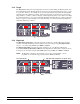
13.1 S3 Expansion Connections LOW VOLTAGE WIRES HIGH VOLTAGE WIRES Stage Connections Battery View of Enclosure Stage Relays PCB 184 Local Network Connection PCB 179 Rear View of Front Panel Backup Connection PCB 168 Address Switches WARNING! Keep All Low Voltage Wires Such As Sensors, Network, & Backup, Curtain Aux Switches Separate From AC Wires! Manual No.
13.2 Setting Address Switches & LED’s on PCB 168 Stage Board PCB 168 Inset B Inset B: Light Emitting Diode (LED) Indicators When the Green Stage LED’s are ON, PCB168 is sending power to the Specific Stage Relay Boards. POWER Status LED ORANGE Backup Power Supply & Main Controller Power Supply Both Connected. RED Main Power Supply Lost GREEN Backup Power Supply Lost Relay Power STATUS LED Always If this LED is not lit then all RED power has been lost.
13.3 Connecting Stage Jumpers of S-3 Expansion Pictured at below is a stage relay board consisting of four stage relays and the associated stage jumper for each relay. The stage jumpers are labeled COOL 1, COOL 2, COOL 3, and HEAT. Location of the jumper places the stage in one of these four modes, or if the jumper is NOT inserted, the stage is NOT placed on Back-up. The jumpers should be placed based on the operation of stage equipment and should be the same as assigned in the Master Controller.
13.4 S3 Expansion PCB179 Circuit Board Layout 3 Amp Slow-Blow Fuse – F2 (for Evolution Back-Up Power Supply) Vent Override Back-Up System to S3 PCB168 Tunnel Override Local Net to S3 PCB168 Connection for Stand-Alone Option Board HH.
13.5 Connecting AC Power Supply to the S3 Expansion 3 Amp Slow-Blow Fuse – F1 (Main Power Supply) S3 Expansion PCB184 Power Supply Inset A Inset A Manual No.
Evolution Controller Evolution S3 16 Stage Expansion Module P 1- 9 G eneral Param eters P1 = Temperat ure Units C = Celsiu s F = Fah renheit P2 = In divid ual Alarm Temp erature L imit s Yes = Temperatu re Limits Set Individually No = T emperature Limits Set Identical P3 = B ack-Up Timer Percen tag e P4 = B ack-Up St age O n Delay P4 = B ack-Up St age O n Delay P 40-49 Hired -Hand Netw ork P40 = HH NET Netw or k Add ress P41 = Soft ware Version Number P42 = Con tr oller Setup P43 = L ocal Network Enable No
13.6 S3 Expansion Stage Power Connection Connecting Power from Breaker to a Heat Stage And a Cool Stage in the S3 Expansion S3 Expansion Top Cabinet Terminal block for stage connections NOTE: Example above shows how to wire stages to heating & cooling equipment. Stage numbers are shown on label affixed to inside top of controller box. WARNING! Keep High Voltage (Or AC) Separate From Low Voltage Wires! Manual No.
13.7 Connecting Sensors to the S3 S3 Expansion PCB179 Inset A Sensors Inset A SENSOR SENSOR SENSOR Manual No.
13.8 S3 PowerTrak Override Settings and Wiring S3 Expansion PCB179 NOTE: If connecting the Back-Up to a relay box instead of PowerTrak, Cut and discard the four components shown. Inset A Vents Override Tunnel Override Inset B PowerTrak INLET MODE Vent Override Cool 1 Tunnel Override Cool 3 Vents & Tunnel Will Wire The Same Inset B Inset A Vent Override for Fail-Safe Action Refer to Section 6.
13.9 Optional S3 Relay Card Wiring (Purchased Separately) S3 Expansion PCB179 Relay Card Inset A Relay Card Six Stand-Off Attachment Holes Wire Terminals Inset A Relay Card Header Connection For Relay Card NOTE: Ensure the Relay Card connector and the PCB header is properly aligned during stand-off and Relay Card installation. NOTE: The Relay Card is necessary on Stand-Alone systems ONLY. If S3 is used in conjunction with Evolution 3000/3001, this relay card is optional. Manual No.
13.10 Connecting an Alarm or Siren to the S3 S3 Expansion PCB179 Inset A Inset A Manual No.
13.11 Connecting Auxiliary Inputs to the S3 S3 Expansion PCB179 Inset B Inset A NOTE: The jumper across J6, J8 and\or J10 must be removed if an external alarm input is connected. Manual No.
13.12 Connecting Other Hired-Hand Controllers to the S3 Expansion Auxiliary Input The diagram below shows the proper way to connect the Hired-Hand family of auxiliary alarm outputs to the S3 Expansion auxiliary inputs. The alarm activates when the connection is broken between the OUT and IN terminals. NOTE 1: As long as a path for current flow is present, the Secondary Sensing System is not activated. Consequently, if one controller alarms, the path will be broken and the alarm will be activated.
13.13 Connecting Local Network Connections to the S3 Expansion Editor Navigator Current Conditions Target Conditions Minimum Vent Stage Conditions ENTER Historical Data Back-Up Status Alarm Status Network Status Program Setup This Product May Be Protected Under One Or More Of The Following U.S.
13.14 Connecting the S3 to the HH.Net S3 Expansion PCB179 Inset B Inset A Manual No.
14.
Terminal Blocks 3006-5077 3006-5078 3006-5079 3006-5092 3006-5082 CONN Terminal Block 3 pos CONN Terminal Block 4 pos CONN Terminal Block 5 pos CONN Terminal Block 6 pos CONN TBLK 3 pos Magnum (Green) Sensors and Wire 1503-2427 6407-6084 6407-6070 CBL SJT 18-2 Yellow (sensor) /Temperature Sensor Junction Box Assy Current Sensor .35-100A (For use with belts, motors, or feed augers.
15. Temperature vs. Sensor Resistance Table The following chart gives the resistance when measured between the white and black sensor wires at a given temperature. To check a sensor, first know the temperature in the area, then, use a multi-meter to check the resistance. Resistance Kohms 32.654 32.158 31.671 31.191 30.72 30.257 29.802 29.355 28.915 28.482 28.057 27.777 27.363 26.957 26.557 26.164 25.777 25.523 25.147 24.777 24.413 24.055 23.82 23.472 23.13 22.793 22.572 22.244 21.922 21.71 21.397 21.
16. Error Codes The controller records errors based on the communications links. When errors occur, an alarm will be generated. Error Codes for the Evolution S3 Error Code Description LnE Local Network Error LnO Local Network Override Error Manual No. 4801-3001 Rev 7-08 Explanation The Back-Up has lost Communications with the Master Controller. NOTE: During this condition the Back-Up will run Cool 1 on a 5 minute timer.
Manual No.