Farm Hand Alert Alarm Owners Manual Hired Hand, Inc. 1733 Co Rd 68 PO Box 99 Bremen, AL 35033 Part No.
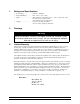
Table of Contents Section Title Page 1. Ratings and Specifications..............................................................................................................................1 2. Warnings.........................................................................................................................................................1 3. Limited Warranty.....................................................................................................................................
1. Ratings and Specifications • • • • 2. Power Supply…………………240VAC 50/60 Hz Temperature Range…………..32°F - 122°F (0°C – 50°C) Inputs………………………....Three thermistor temperature sensors 32°F – 120°F (0°C - 49°C) One water meter (contact closure) Two auxiliary inputs (contact closure) Outputs………………………..One siren (1.
. Introduction The Farm Hand Alert Alarm Controller is an automatic audible alarm system that can trigger an alarm from temperature, water flow, power outage or other auxiliary contacts connected remotely to the controller. Individual adjustments provide for setting the high and low temperature limits for each sensor and the high and low water flow rates. A front panel display contains status, temperature, and water quantity indicators plus test functions.
4.2 Display Indicator The type of information in the Channel Display is shown by the green LED’s in the Display Indicator. For example, if the green light beside “Actual Reading” is lit, then the Channel Display is showing the current reading from a sensor. The other options for the Display Indicators are High Limit, Low Limit and Reset. These are changed by momentarily pressing the Mode button as discussed in the next section.
5. General Overview 5.1 Alarm Inputs The Alert Alarm has seven inputs that can be used to sound an alarm. Three from temperature sensors, one water quantity, two auxiliaries and one for power out. The water quantity and temperature sensors can be enabled or disabled. If a sensor is enabled it will be used to generate an alarm. If a sensor is disabled, it will not generate an alarm, even if the Alert Alarm determines that its readings are out of limits.
5.1.4 Power Out The Power Out alarm indicates that there has been no electricity present on the alarm power feed for at least one minute. If it is found that there is power at the electrical outlet, the 2 Amp fuse located on the Alert Alarm circuit board (F1) could be blown. If this is the case, remove power for approximately 30 seconds, then reapply power. This should reset the fuse. The Alert Alarm will wait 60 seconds after a Power Out indication before triggering an alarm. 5.
the Alert Alarm can have different high and low limit setpoints. For Water Quantity, the Display Indicator shows the current setting for the high limit setpoint. To adjust these settings, press the Mode button until you see the green LED beside the High Limit on the Display Indicator. Note the Select button next to the sensor or parameter setting you want to adjust.
When you are finished setting the Water Total, press the Mode button and the new setting will be stored in the Alert Alarm. If you do not press the Mode button within 10 seconds, the Alert Alarm will return to the ”Actual Reading” and any changes you have made will not be remembered. 6.2 Water Total Readings The Water Total indicator counts the total quantity of water recorded by the water quantity sensor. This reading does not have a high or low limit setpoint and can not be used to set off an alarm.
To display this information, make sure the Display Indicator LED is indicating “Actual Reading”. Then press any Select button. High Temperature Reading Select Button Alarm LED The Channel Display for the temperature and water rate will indicate the highest reading recorded since the History Record was reset as shown in the example at the right for Sensor 1. For the high limit there is an “H” on the left of the display.
8.1 General Parameters General parameters are associated with the operation and control of the Alert Alarm. P1 – Individual Sensor Limits This general parameter determines how to program the Sensor High and Low temperature limits. As indicated earlier, these limits can be set individually to different values. However, if it is desired to set Sensor 1, Sensor 2, and Sensor 3 to the same values, this parameter changes the programming procedure to allow limits to be entered only once but used for all sensors.
9. Recommendations It is important to note the Hired Hand temperature sensors are fabricated using thermistors and are not interchangeable with sensors commonly used on controllers from other manufacturers. The three temperature sensors may be installed in a variety of ways. It is recommended that a sensor be located high enough from the floor so that livestock or poultry can not peck at it.
Trouble-Shooting the Auxiliaries The auxiliary inputs must always form a closed loop circuit. If the loop is ever open, the alarm will sound. If an auxiliary input is sounding, the trouble can be isolated between the alarm and the circuit by disconnecting the circuit from the terminal block in the alarm box and replacing it with a jumper (See Section 13.5). If the corresponding auxiliary input still causes an alarm condition, the problem is the alarm, otherwise the circuit is the culprit. 11.
10. If using a modem, connect wires from Modem terminals to the modem circuit or relay box. (See wiring diagrams in Section 13.5 for locations of terminals.) 11. If necessary, connect the Alert Alarm to the Hired Hand inter-controller Network or to the Data Shuttle, (See the connections in Section 13.8 of this manual.) 12. Maintenance Check the calibration of your temperature sensors at least once per quarter.
Part No. 4801- 5085 Rev 5-01 Farm Hand Alert Alarm Water / Lights Aux 1 / Aux 2 Lights, Aux 1, Aux 2, & Metric Jumpers Alarm/Siren Net term Jumper Sensors HH.Net FARM HAND ALERT ALARM Battery AC Power Connector Transformer 13.
13.2 Connecting AC Power to the Alert Alarm Farm Hand Alert Alarm Inset A Inset A Part No.
13.3 Connecting Sensors to the Alert Alarm Farm Hand Alert Alarm Jumper Metric J2 Jumper Installed Vacant Temperature Units Farenheit Celsius Inset A Part No.
13.4 Connecting an Alarm or Siren to the Alert Alarm Farm Hand Alert Alarm Inset A Inset A Red NO NC Siren White (-) White Alarm Out Internal Switch (Non-alarm) position Red (+12V) Siren Connect to alarm, modem, autodialer,etc. as desired. Com Part No.
13.5 Connecting External Inputs to the Alert Alarm Farm Hand Alert Alarm Inset B Inset A NOTE: The jumper across J6 and\or J8 must be removed if an external alarm input is connected. Part No.
13.6 Connecting Other Farm Hand Controllers to the Alert Alarm Farm Hand Alert Alarm Series Alarm Connection The diagram below shows the proper way to connect the Farm Hand family of auxillary alarm outputs to a Farm Hand Alert Alarm. The alarm activates when the connection is broken between the OUT and IN terminals. Aux1 or Aux 2 Alarm N.O. N.C. Alarm N.C. N.O. Com N.C. N.O. Aux Alarm N.C. N.O. Aux Alarm Note 1: As long as a path for current to flow is present, the Alert Alarm is not activated.
13.7 Connecting the Alert Alarm to the HH.Net or to a Data Shuttle Farm Hand Alert Alarm Inset A Inset B Part No.
13.8 Connecting the Alert Alarm to the Water Meter and Light Control Warning! The external relay is not supplied for the light circuit. Do not apply high voltage AC to the “Light Sig” input! Farm Hand Alert Alarm Inset B Inset A Jumper J11 is used to represent a “Lights On” condition. If a Light Program is used, J11 must be removed and the circuit shown in “Light Control” should be added. Part No.
Internal Connection Diagram 14. Replacement and Optional Parts Farm Hand Alert Alarm 13.9 Farm Hand Siren Driver/Speaker…………………….………Product # 3016-1380 Farm Hand Water Quantity Meter…………………………...Product # 3025-0101 Farm Hand Temperature Sensor……………………….…….Product # 6407-2593 Battery for the Alert Alarm…………………………………..Product # 3014-2174 Part No.
15. Temperature vs. Sensor Resistance Table The following chart gives the resistance when measured between the white and black sensor wires at a given temperature. To check a sensor, first know the temperature in the area, then, use a multi-meter to check the resistance. Resistance Kohms 32.654 32.158 31.671 31.191 30.72 30.257 29.802 29.355 28.915 28.482 28.057 27.777 27.363 26.957 26.557 26.164 25.777 25.523 25.147 24.777 24.413 24.055 23.82 23.472 23.13 22.793 22.572 22.244 21.922 21.71 21.397 21.
16. Farm Hand Alert Alarm Program Label Programming (Alert Alarm) P 1-9 General Parameters P1 = Individual Temperature Limits Yes= Temp Limits are Set Individually No= Temp Limits are Identical P 40-49 Hired Hand Network P40 = Network Address P41 = Software Version P42 = Controller Setup PS Sensor Calibration PS1 = Sensor 1 PS2 = Sensor 2 PS2 = Sensor 3 To view History: Press any "Select" button while the Green Display Indicator is showing "Actual Reading".