PT Controller Curtain Actuator Hired Hand, Inc. 1733 Co Rd 68 PO Box 99 Bremen, AL 35033 Part No.
Table of Contents 1. 2. 3. 4. 5. Warnings................................................................................................................................................. 1 Limited Warranty .................................................................................................................................... 1 Physical Description ................................................................................................................................ 2 Use of Equipment .
1. Warnings Warning! When this controller is used in a life support heating and ventilation system where failure could result in loss or injury, the user should provide adequate back-up, or accept the risk of such loss or injury! Warning! Wiring and connections must comply with all national and local electrical codes. Installation by qualified electrician required! Warning! Electrical shock may occur if the enclosure is opened with power connected to the unit.
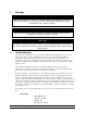
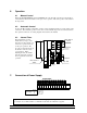
3. Physical Description The PT Controller is shown below both closed and with the door open. The major components are labled as well. Close Relay Open Relay TM POWER CURTAIN CONTROLLER Remote Curtain Control 10 AMP FUSE AUTOMATIC OPERATING INSTRUCTIONS MANUAL For Automatic Use: Set Automatic/Manual Switch to Automatic and thermostat to desired temperature. Close For Manual Use: Set Automatic/Manual Switch to Manual and Manual Switch to Open or Close.
6. Operation 6.1 Manual Control When the Automatic/Manual switch is in Manual, the controller will open and close the curtains or vents whenever the bottom switch is in its open or close position. The center position of the switch is the off position. 6.2 Automatic Control To place the PT Controller in automatic operation, select Automatic with the top toggle switch on the control box. The terminals (position 4, 5, 6, and 7 on the terminal strip) need to be connected before this operation will work.
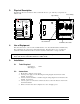
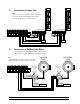
8. Connection of Power Trak Note: Unit 1 connection is identical to unit 2 shown below. To reverse the direction interchange the terminal positions 9 &10 (unit 1) or 12 & 13 (unit 2). PowerSupply Thermostat/Control 11 12 Hot IN UNIT 1 13 CLOSE 10 OPEN 9 CLOSE 8 Hot IN OPEN (Ground) RED 7 GREEN 6 (Close) 5 (Open) 4 BLACK 3 WHITE 2 L1 L2 (Common ) 1 GND 14 15 UNIT 2 POWER SUPPLY 9.
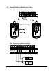
10. Control Signals for Models with Timer 10.1 Connection of Thermostat NOTE: Two types of thermostats can be used, a Single Stage or Two Stage 10.2 1 GND Connection to Stages for Control 2 3 4 5 6 7 L1 L2 Power Supply Thermostat/Control Part No.
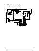
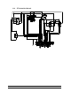
11. PT Controller Internal Wiring Diagram 11.1 PT Controller 120 volt Part No.
11.2 PT Controller 240 volt Part No.