
User guide
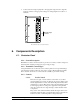

Contactor Control Systems 6
STAGE STAGE STAGE STAGE
COOL
HEAT
GND
COOL
HEAT
GND
5
6
7
8
STAGE STAGE STAGE STAGE
COOL
HEAT
GND
COOL
HEAT
GND
1
2
3
4
HIRED-HAND
R
-
+
ALARM
AC
SENSOR
+
-
COOL 2 COOL 1
HEAT
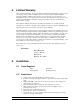
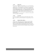
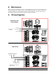
Wiring Diagram for Two
Stage Cool Back-Up
When the back-up is wired in this manner,
and the switches are aligned as shown,
stages 3 and 4 would come on when
the back-up board calls for Cool 1.
When the back-up board calls for Cool 2
the remaining cool stages would start.
This board found on back of
CCS Panel door.
Œ
•
Œ
•
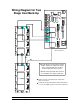
Remove the wire connecting the two relay boards
at the cool positions.
Install new wire from the backup board position labeled
cool 2, to the "COOL" position on the lower relay board..