
User guide

Contactor Control Systems 8
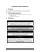
8. Maintenance
There are few items on the CCS panel which require maintenance. This does not mean that maintenance is
unimportant. Remember that the more time you spend making things right, the less time you will spend
correcting problems. To prevent malfunctions of the contactor panel, keep your panel clean and free of
debris. Follow all safety warnings when working with electrical equipment.
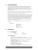
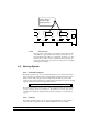
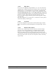
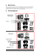
9. Wiring Diagrams
LIGHTS
COMMON
120VAC HOT
120VAC NEUT
GROUND
FAN
CONTROL
MICRO
SWITCH
OUTIN
L1 L2 L1 L2 L1 L1
OUTIN
L2 L1 L2
IN
L2
Stage 1 5 9 Stage 2 6 10 Stage
LIGHT 1 LIGHT 2
IN OUT IN OUT
Contactor Panel
Power Supply
L1 (Hot)
L2 (Neutral)
Ground
From Breaker
Panel
LIGHTS
COMMON
120VAC HOT
120VAC NEUT
GROUND
FAN
CONTROL
MICRO
SWITCH
OUTIN
L1 L2 L1 L2 L1 L1
OUTIN
L2 L1 L2
IN
L2
Stage 1 5 9 Stage 2 6 10 Stage
LIGHT 1 LIGHT 2
IN OUT IN OUT
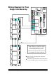
From Breaker Panel
Line 1Line 2
Line 2
Line 1
To Stage Load
Repeat for all four, eight, or
twelve stages.
Stage Wiring