Owner's Manual R Radiant Brooder with Pilot Ignition Models BJ-C-32-SPI BJ-C-42-SPI If you smell gas: 1. 2. 3. 4. Open windows. Don't touch electrical switches. Extinguish any open flames. Immediately call your gas supplier. Si vous sentez une odeur de gaz: 1. 2. 3. 4. Ouvrez les fenetres. Ne touchez pas aux interrupteurs electriques. Eteignez toute flamme nue. Contactez immediatement votre compangie de gaz.
Table of Contents 1. RATINGS AND SPECIFICATIONS.......................................................................................................1 1.1. RATINGS ................................................................................................................................................1 1.2. GAS PRESSURE REQUIREMENTS ............................................................................................................1 1.3. CAUTION! MINIMUM CLEARANCES ...........................
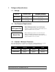
1. Ratings and Specifications 1.1. Ratings Minimum Ventilation Model No. Maximum Input BJ-C-32-SPI 32,000 BTUH (9.38 kW) 320 CFM/brooder 3 (543.6 m /hr) BJ-C-42-SPI 42,000 BTUH (12.31 kW) 420 CFM/brooder 3 (713.6 m /hr) (Air required to support combustion) 1.2. Gas Pressure Requirements LP/Propane Gas: Burner manifold gas pressure is to be 11 in. W.C. [27.4 mbar] at maximum input rating.
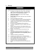
2. Warnings WARNING! Read and understand all the following precautions before installing or operating this Unit. 1. 2. 3. 4. 5. 6. 7. 8. 9. 10. 11. 12. 13. 14. 15. 16. Installation must comply with all local, state, and national codes. In the absence of local codes, in accordance with CAN1-B149.1 or 2 Installation Codes (Canada). Follow safety, maintenance, and test firing instructions packaged with brooder. Refer to model specifications label for gas type (LP/Propane or Natural Gas).
3. Limited Warranty All products are warranted to be free from defects in material and workmanship if installed and used in strict accordance with the installation instructions. Liability is limited to the sale price of any products proved to be defective or, at manufacturers option, to the replacement of such products upon their return. No products are to be returned to the manufacturer, until there is an inspection and a return goods authorization (RGA) number is issued.
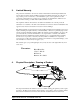
All controls are located on the gas valve mounted on top of the brooder canopy. There are three controls you will use: the control knob, pilot purge button, and the thermostat knob, see illustration below. The control knob is located on the back side of the gas valve and has three positions: ON, OFF, and PILOT. The pilot purge button is the spring loaded red button located beside the control knob. The thermostat knob is located on top of the gas valve, and is adjustable from 1 (Low) to 9 (High).
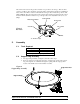
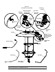
3. 5.3. Rotate the suspension rod until the swaged portion mates with the opening, push the suspension rod through the opening so that the opening is between the swage, then rotate the suspension rod so that it is positioned with the mounting pedestals pointing inwards toward the center of the support ring, as in Figure 3. Burner Unit Assembly 1. 2. For burner unit assembly, see Figure 3, then follow these steps.
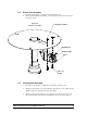
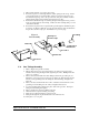
5.4. Burner Unit Assembly 1. 2. For burner unit assembly, see Figure 4, then follow these steps. Position pilot bracket as shown in Fig. 4. Secure with two 8-32 X 1/2 screws and 832 nuts (provided). Figure 4 Burner Assembly 8/32 Kep Lock Nuts Pilot Bracket Thermocouple Pilot 8/32 x 1/2 Screws 5.5. Final Brooder Assembly 1. For final brooder assembly, see Figures 5 and 6. Then follow these steps. 2. Attach gas valve bracket to gas valve with three 10-24 X 1/4” screws.
Figure 5. Final Brooder Assembly Capillary Tubing Gas valve bracket and gas valve.
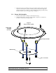
3. 4. 5. 6. Place ceramic element on top of the support ring. Insert the suspension rods through the three slotted openings in the canopy. Insert a cotter pin through the second and smaller opening in each of the suspension rods, then bend the longer leg of the cotter pin to the side. The pilot assembly should be aligned with the burner unit assembly, when facing the gas valve. Insert thermostat bulb through one retaining clamp, then through the holes provided in the gas valve bracket as shown in Fig. 5.
6. Installation Installation of your assembled brooder involves two steps: 1. Hanging the Unit 2. Gas Tube Hookup First we have an example drawing of how to hang the unit, then the next section covers gas hookup, including checking that the gas supplied to the unit is at the correct pressure. Remember to follow all safety precautions when hanging the unit, and hooking up the gas supply. 6.1. Hanging the Unit 6.1.1.
6.1.2. Hanging SPI Galvanized Brooder with 34” Diameter Canopy The hanging kit for the 34” diameter galvanized steel brooder canopy includes an 11” chain and two 6” chains which must be attached as shown in Fig. 8 to ensure that the canopy will hang level. Join the three chains at the center of the canopy with a single S-hook. Connect the two 6” chains (with S-hooks) to the holes in the tops of the left and right suspension rods.
6.2 Gas Hookup 6.2.1 Connection of gas hose to brooder The brooder’s gas valve does not regulate the gas pressure. You must provide a regulator to keep manifold pressure at the rated pressure (see ratings on page one of this manual) for proper operation. The following flowchart shows the minimum equipment for the operation of one brooder.
7 Operating instructions 7.1 Placing Brooder in Service 1. 2. 3. 4. 5. 6. 7. 8. 7.2 Check that all installation steps in section 6 of this manual have been performed. Read and understand warning statements in section 2. Open gas supply valve. Turn control knob on gas valve to the PILOT position. Press and hold red pilot purge button all the way in. Hold a flame close to the pilot hood to ignite the pilot. Hold in the pilot purge button for at least 30 seconds after lighting pilot.
9 Troubleshooting Guide Symptom Pilot will not remain lit. Main burner will not ignite. Possible Cause Pilot orifice may be restricted. Clean the orifice. Thermocouple is not sensing the pilot flame. Replace thermocouple. Thermocouple misaligned Check thermocouple position. If problem persists, replace thermocouple. Thermostat may not be set properly. The control knob may be in the PILOT position. The burner venturi may be restricted. Pilot flame may not reach the burner. Faulty gas valve.