
User Manual

HIRED-HAND, INC. • 1733 County Road 68 • Bremen, AL 35033 • PHONE 256-287-1000 • FAX 256-287-2000
Manual Part No. 4801-0173 Rev 9-00
SS
SS
II
II
NN
NN
GG
GG
LL
LL
EE
EE
CC
CC
EE
EE
II
II
LL
LL
II
II
NN
NN
GG
GG
II
II
NN
NN
LL
LL
EE
EE
TT
TT
TT
TT
oo
oo
oo
oo
ll
ll
ss
ss
RR
RR
ee
ee
qq
qq
uu
uu
ii
ii
rr
rr
ee
ee
dd
dd
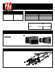
Variable Speed Drill 1/4" Hex Socket
Cut Opening For Ceiling Inlet
SS
SS
ii
ii
nn
nn
gg
gg
ll
ll
ee
ee
CC
CC
ee
ee
ii
ii
ll
ll
ii
ii
nn
nn
gg
gg
II
II
nn
nn
ll
ll
ee
ee
tt
tt
PP
PP
aa
aa
rr
rr
tt
tt
ss
ss
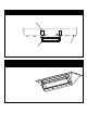
6609-2000 Single Ceiling Inlet 0006-5026 Small louver
4003-6002 Frame 104805001 Pin (Small Louver)
0006-5025 Large louver 1048-5000 Pin (Large Louver)
1004-5027 Screws 4003-6000 Housing
1. Determine the location in ceiling to install
the ceiling inlet.
2. Cut an opening to the following specification
for a single ceiling inlet.
Adjustment Of Power DriverAdjustment Of Power Driver
Installation Of Frame Into Ceiling InletInstallation Of Frame Into Ceiling Inlet
Cut Opening To These
Dimensions
5-3/4 in.
22-1/2 in.
1. Position frame to place large louver at
top, close to the flange of housing.
2. Fit frame assembly into opening of
ceiling inlet housing.
3.
Install eight (8) fasteners through holes
in frame assembly.
IMPORTANT!
Use drill setting as described above to
avoid stripping plastic screw holes.
Ceiling Inlet Housing
4003-6000
Large louver
0006-
5025
Small louver
0006-5026
Frame 4003-6002
Drill Adjustments Vary. Use this
as
example only
of how to gauge adjustment
of your particular drill/driver.
IMPORTANT!
SET DRIVER TORQUE TO LOW SETTING. For
example, a typical multi-
speed driver may
provide 20 settings plus a "Drill" (solid-
lockup)
setting. Lowest torque is available at setting
1, with Maximum torque available at "Drill"
setting. IMPORTANT!
SET TORQUE TO LOW
RANGE OF 5 TO 7 TO DRIVE SCREWS.
Hi/Lo switch
Set To Lo
Settings
Screws
1004-5027