
User Manual

33
────────────────────────────────────────────────────
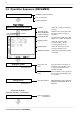
3.2 Operation Sequence ( REC&MEM)
────────────────────────────────────────────────────
1
2
3
4
5
6
7
8
9
10
11
12
13
14
A
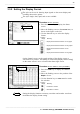
Settings on the channel screen
Setting the input channel
Setting the trigger function
Start measurement
Stop measurement
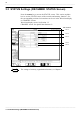
Setting the system
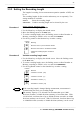
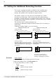
Press the
START
key and the LED lights.
When the trigger conditions are met, measurement start.
Press the
STOP
key and the LED goes out after measurement has finished.
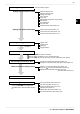
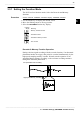
Waveform display color
Waveform display graph
Voltage axis range
Input coupling
Logic input
Magnification/compression along voltage
Zero position
Zero adjustment
Low-pass filter
Variable function (See Section 5.2)
Settings the advanced function
Scaling function (See Section 5.3)
Comment function (See Section 5.4)
Vernier function (See Section 5.6.3)
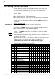
Trigger mode
Trigger source
Pre-trigger
Trigger selection
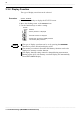
Processing measurement data
Printing the measurement data (See Chapter 10)
Saving the measurement data (See Quick Start Chapter 10)
Measurements on display screen
Waveform scrolling (See Quick Start Section 8.1)
Using the A B cursor (See Quick Start Section 8.2)
Magnification/compression ratio along time axis
(See Quick Start Section 8.3)
Set up (See Quick Start Section 9.2)
File (See Quick Start Section 9.3)
Printer (See Quick Start Section 9.4)
Interface (See Chapter 11)
Initialize (See Quick Start Section 9.5)
Self-check (See Quick Start Section 9.6)
Press the
SYSTEM
key to display the
SYSTEM screen. (See Quick Start Chapter
9)
See Quick Start
Cha
p
ter 7
See Quick Start Chapter 6