
User Manual

16
────────────────────────────────────────────────────
2.4 Connection of the Input Product
────────────────────────────────────────────────────
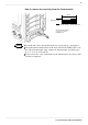
CAUTION
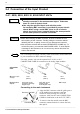
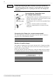
When disconnecting the BNC connector, be sure to release the
lock before pulling off the connector. Forcibly pulling the connector
without releasing the lock, or pulling on the cord, can damage the
connector.
Connector
g
uide
Groove of the
BNC
Conversion cable Clamp-on sensor/probe
9318 9270, 9271, 9272, 9277, 9278, 9279
Clamp Number
3274 CLAMP ON PROBE
Continuous 150 A
Non-continuous 300 A
8
4
3273-50, 3275, 3276 CLAMP ON PROBE 4
9278 UNIVERSAL CLAMP ON CT 7
9279 UNIVERSAL CLAMP ON CT 7
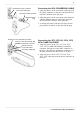
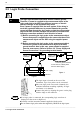
Connecting the Connection cord
(for voltage measurement)
1. Align the BNC connector with the guide groove of
the 8855 input connector, and turn clockwise while
pressing in to lock the connector.
(For using the 8951, use the 9198 CONNECTION
CORD.)
2. To remove from the module, turn the BNC
connector counterclockwise to release the lock,
then pull it.
Connecting the Clamp (for current measurement)
The following clamp-on sensors and clamp-on probes can be connected
using the 9318 CONVERSION CABLEs.
Number of usable clamps
The number of clamps that can be used with the 8855 is limited according
to clamp type. The clamps that can be used for the relevant clamp type is
shown to the list shown below.
In the case that the relevant clamp type is used the clamp total use number
is confirmed and please do not exceed the number of the list shown below.