
User Manual


vii
────────────────────────────────────────────────────
Notes on Use
────────────────────────────────────────────────────
DANGER
External I/O terminal connections
A common GND is used for the external I/O terminals (START,
STOP, GO, NG, EXT_OUT, EXT_TRIG, EXT_OUT, and EXT_SMPL
terminals) and the 8855 instrument. The terminals are not
isolated. To prevent damage to the object connected to the
external I/O terminals and the 8855 instrument, wire the
terminals so that there is no difference in electrical potential
between the GND for the external I/O terminals and the GND for
the connected object.
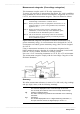
Logic Probe Connection
The logic input and 8855 instrument share a common ground.
Therefore, if power is supplied to the measurement object of the
logic probe and to the 8855 from different sources, an electric
shock or damage to the equipment may result. Even if power is
supplied from the same system, if the wiring is such that a
potential difference is present between the grounds, current will
flow through the logic probe so that the measurement object and
8855 could be damaged. We therefore recommend the following
connection method to avoid this kind of result. Refer to Section
2.5, "Logic Probe Connection" for details.
(1) Before connecting the logic probe to the measurement
object, be sure that power is supplied from the same outlet
box to the measurement object and the 8855 using the
supplied power cord.
(2) Before connecting the logic probe to the measurement
object, connect the ground of the measurement object to the
8855 ground terminal. Also in this case, power should be
supplied from the same source. Refer to Section 2.2, "Power
Supply and Ground Connections" for grounding terminal
details.
Differential Probe Connection
When using grabber clips, the 9322's maximum rated voltage
to earth is 1500 V AC or DC (CAT ll) / 600 V AC or DC (CAT lll);
when using alligator clips, it is 1000 V AC or DC (CAT ll) / 600
V AC or DC (CAT lll). To avoid electrical shock and possible
damage to the instrument, never apply voltage greater than
these limits between the input channel terminals and chassis,
or across the input of two 9322s.
Maximum input voltage is 1000 V AC/2000 V DC (CAT ll) / 600
V AC or DC (CAT lll). Attempting to measure voltage in excess
of the maximum rating could destroy the instrument and
result in personal injury or death.