
User Manual

128
────────────────────────────────────────────────────
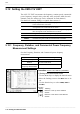
5.12 Setting the 8955 F/V UNIT
────────────────────────────────────────────────────
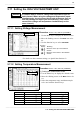
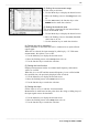
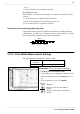
5.12.3 Pulse Duty Ratio Measurement Settings
Object to be
measured
Measurement range
DUTY 5% (fixed)
Function
display
Meaning
:
Move the cursor up in the selection
window.
:
Move the cursor down in the selection
window.
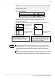
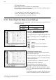
(5) Setting the slope
Set the slope to use as a reference for measurement.
Measurement is made based on the point where the rising or falling slope of
the input signal crosses the threshold.
1. Use the Menu keys to display the desired screen.
2. Move the flashing cursor to the
Slope
item to be set.
3. Use the function keys to make the selection.
The pulse duty ratio measurement is the ratio between the measured HI level
and LO pulse levels.
Procedure
Screen: LIST, ONE CH (CHANNEL)
(1) Setting the measurement mode
1. Use the Menu keys to display the desired screen.
2. Move the flashing cursor to the
Mode
item to be
set.
3. Use the function keys to select
DUTY
.
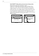
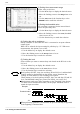
(2) Setting the threshold value
The waveform is measured for the interval that it
crosses the pulse duty ratio.
1. Use the Menu keys to display the desired screen.
2. Move the flashing cursor to the
Level
(threshold
value) item to be set.
3. Use the function keys to make the selection.
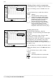
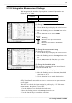
(3) Setting the pull-up resistance
Pull-up resistance is used when the 8855 is
connected to an open-collector output signal.
When ON is selected, the input terminal is pulled
up by +5V. With most measurements, this option is
set to OFF.
1. Use the Menu keys to display the desired screen.
2. Move the flashing cursor to the
Pull Up
item to