
User Manual

111
────────────────────────────────────────────────────
5.6 Setting the Waveform Display Screen
────────────────────────────────────────────────────
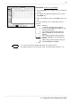
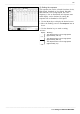
5.6.1 Entering by F9 (CH.SET) Key
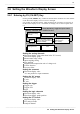
Waveform display screen
Setting the analog
channel
Setting the logic channel
Setting the X-Y
(
X-Y screen
)
OFF
Press the
F9
ke
y,
to
gg
le the in
p
ut screen.
Comment
Setting the trigger
Settin
g
the FFT
OFF
Memor
y,
Recorder
,
REC & MEM Function
FFT Function
Setting the power monitor
(when the 9549 FUNCTION UP
DISK is installed
)
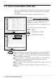
5.6 Setting the Waveform Display Screen
Pressing the
F9
(
CH.SET
) key, enables the measurement conditions for each channel
on the Waveform display screen to be set or changed.
It is possible to make the settings, while monitoring the waveforms in real time on
the Waveform display screen. For details on settings, refer to Section Quick Start
6.3.
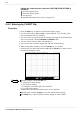
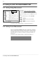
Setting the analog channels
Waveform display color (other than in the X-Y screen)
Waveform display graph
Measurement range setting
Input coupling setting
Zero position
Magnification/compression ratio of voltage axis.
Vernier function
Low-pass filter
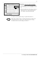
Setting the comment
Waveform display color
It is not possible to input comments.
Setting the X-Y screen
Waveform display color
X axis
Y axis
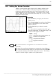
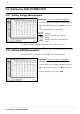
Setting the trigger
Trigger type
Trigger level
Slope
Setting the logic channels
Waveform display color
Waveform display graph position
Setting the FFT screen
Waveform display color
FFT analysis mode
Analysis channel