
User Manual

98
────────────────────────────────────────────────────
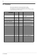
5.1 Overview
────────────────────────────────────────────────────
Item Screen Channel Display
Waveform Display Color
z
z
See Section Quick Start 6.3.1
Print Density
z
z
See Section Quick Start 6.3.2
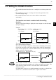
Waveform display screen
z
-
See Section Quick Start 6.3.3
When the display format setup on
Status screen.
Measurement Mode
z
-
See Section Quick Start 6.3.4
Measurement Range
z
z
See Section Quick Start 6.3.5
Input Coupling
z
z
See Section Quick Start 6.3.6
Magnification/Compression
Ratio Along the Voltage Axis
z
z
See Section Quick Start 6.3.7
Zero Position
z
z
See Section Quick Start 6.3.8
Low-Pass Filter
z
z
See Section Quick Start 6.3.9
Logic Display Color
z
z
See Section Quick Start 6.3.10
Logic Display Position
z
z
See Section Quick Start 6.3.10
Zero Adjustment
z
z
See Section Quick Start 6.4
Variable Function
z
-
See Section 5.2
Scaling Function
z
-
See Section 5.3
Comment function
z
-
See Section 5.4
Vernier
-
z
See Section 5.6.3
Probe
z
-
See Section 5.7
Response
z
-
See Section 5.9 (8952 only)
AAF
z
-
See Section 5.10 (8953-10 only)
RJC
z
-
See Section 5.11 (8954 only)
Burn Out
z
-
See Section 5.11 (8954 only)
Threshold value
z
-
See Section 5.12 (8955 only)
Pull-up
z
-
See Section 5.12 (8955 only)
Hold Function
z
-
See Section 5.12 (8955 only)
Slope
z
-
See Section 5.12 (8955 only)
Functions
z
z
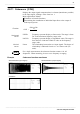
5.1 Overview
This section describes the various input channel settings.
This manual describes the advanced functions of the 8855.
For information on commonly used functions, refer to the Basics edition
(Quick Start Manual) of this manual.