
Quick Start Guide

37
────────────────────────────────────────────────────
Useful Information
────────────────────────────────────────────────────
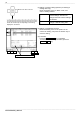
The resolution of the 8950, 8951, and 8952 with a voltage axis of 1 DIV is 100 (100 LSB).
The full scale of the screen is 20 DIV, so the resolution is 2000 LSB (at a voltage axis
magnification rate of 1).
(Example) With a voltage axis of 5 V/DIV, the minimum resolution is as follows: 5 V / 100 = 50
mV.
The resolution of the 8953-10 with a voltage axis of 1 DIV is 1600 (1600 LSB).
The full scale of the screen is 20 DIV, so the resolution is 32000 LSB (at a voltage axis
magnification rate of 1).
(Example) With a voltage axis of 5 V/DIV, the minimum resolution is as follows: 5 V / 1600 =
3.125 mV.
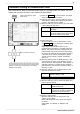
For further details, refer to 6.3.8 "Setting the Zero Position" in the Quick Start
Manual.
5. About the voltage axis and resolution
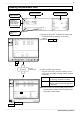
The 8855 is equipped with an SVGA (800 x 600) LCD. The waveform area uses 750 dots
horizontally and 500 dots vertically. As there are 30 DIV horizontally and 20 DIV vertically, one
grid (1 DIV) on the screen measures 25 dots horizontally and 25 dots vertically.
1 grid (1 DIV) on the screen: 25 dots horizontally x 25 dots vertically
1 grid (1 DIV) in data: 100 sample s horizontally x 100 LSB vertically
The grid size (1 DIV) of data changes according to the magnification/compression of the time
axis and voltage axis.
6. About the screen display and DIV
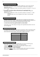
The following shows the speeds of saving binary data (reference values) using different media
and interfaces. Note that the data saving speed varies depending on the saving conditions,
device manufacturer, device capacity, communication conditions, and others.
7. Data saving speed
Storage media Saving speed
(reference value)
Floppy disk 15 kB/s
MO disc 150 kB/s
HD 160 kB/s
PC card 200 kB/s
PC via LAN 200 kB/s
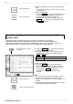
When using Model 9665 10:1 Probe or Model 9666 100:1 Probe and conducting probe
compensation, please configure according to the following settings:
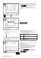
1. Press the
SYSTEM
key to display the Set up screen (refer to "System screen").
2. Move the flashing cursor to the "EXT.OUT" item.
3. Use the function keys to select the
Calibration
.
Based on these settings, a 1 kHz 5 V rectangular waveform will be output from the external
output terminal (EXT.OUT terminal) in order to compen sate the probes.
8. Conducting probe compensati on