
Quick Start Guide

2
────────────────────────────────────────────────────
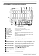
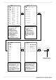
Identification of Controls and Indicators
────────────────────────────────────────────────────
1 2 93 4 5 6 7 8 10 11 12 13 14 15 16 17
1819202122
23
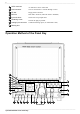
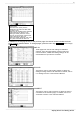
Right Side Panel
1
Power switch
Switches on or off the power supply.
2
AC connector
The supplied power cord must be plugged in here.
3
Function ground
terminal (GND)
Connects to the earth.
4
External sampling
terminal
Allows input of an external sampling clock. (in the Memory
function)
5
Trigger terminals
Can be used to synchronize multiple products, using the EXT
TRIG input and TRIG OUT output.
6
PC card slot
Inserts the PC card.
7
Logic probe connectors
Input connector for the logic input section, designed for the
dedicate logic probes (CH A to D).
8
Eject button
Removes the PC card.
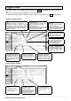
9
External output te rminal
Various output signals can be selected, such as the BUSY, storage,
or probe offset (1 kHz, 5 V Rectangle wave output)
10
NG evaluation output
terminal
When NG results from the numerical evaluation and waveform
evaluation, a signal is output from this terminal.
11
GO evaluation output
terminal
When GO results from the numerical evaluation and waveform
evaluation, a signal is output from this terminal.
12
Ground terminal (GND)
Uses with
9
to
14
(except
12
)terminals.
13
External stop terminals
Stop operation can be controlled.
14
External start terminals
Start operation can be controlled.
15
Key lock
Locks the operation of keys.
Identification of Controls and Indicators