
Quick Start Guide

14
────────────────────────────────────────────────────
Measurement Method
────────────────────────────────────────────────────
Simple measurement operations
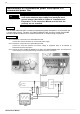
The following describes the simple operating procedures with a waveform input into Channel 1
(CH1) of the 8855 HiCORDER.
(Example) Input of a sine wave of 1 kHz and 1 V, and observation of the waveform
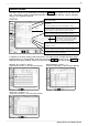
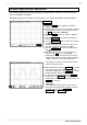
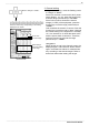
(1) Press the DISP key to display the waveform
display screen.
(2) Move the flashing cursor to the "Function" indication
at the upper left corner of the screen, then press
the F1
key and select "Memory."
(3) Press the CH1
button key of the CH. SELECT
key.
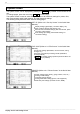
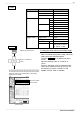
(4) Turn the RANGE
knob to set the voltage axis
range to "200 mV/DIV."
(5) Turn the POSITION
knob to set the zero position
to " 50%."
The above settings set the full scale (upper- and
lower-limit values) on the display to "
2V."
(6) Turn the TIME /DIV
knob to set the ti me axis to
"100 µs/DIV."
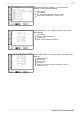
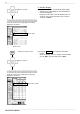
(7) Move the flashing cursor to "Trig" in the screen,
and press the F3
key to set to "AUTO."
Regarding the trigger setting method, refer to the
"Trigger screen" section of this manual or Chapter 7
"Trigger Functions" in the Quick Start Manual.
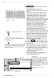
The settings for waveform observation have been
entered in the above steps.
(8) Start measurement. Press the START
key located
at the lower right corner of the front panel. The
green LED located next to the START
key remains
lit while waveform data is being acquired.
(9) To abort the measurement, press the STOP
key
located n e x t t o t h e START
key. When the
measurement is aborted, the green LED next to the
START
key turns off.
< Key point >
The voltage axis range, position, and time axis
range can be changed during a starting operation.
To make changes, use the RANGE
,
POSITION
, and TIME/DIV knobs.
Procedure