GUIDE BOOK 8855 MEMORY HiCORDER
1 ──────────────────────────────────────────────────── Introduction Thank you for purchasing the HIOKI "8855 MEMORY HiCORDER." To obtain maximum performance from the product, please read this manual first, and keep it handy for future reference. About This Manual The manual "Measurement Guide for the 8855" contains the minimum information necessary for operation of the 8855 MEMORY HiCORDER.
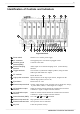
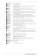
2 ──────────────────────────────────────────────────── Identification of Controls and Indicators 22 21 20 19 18 23 1 2 3 4 5 6 7 8 9 10 11 12 13 14 15 16 17 Right Side Panel 1 Power switch Switches on or off the power supply. 2 AC connector The supplied power cord must be plugged in here. 3 Function ground terminal (GND) Connects to the earth. 4 External sampling terminal Allows input of an external sampling clock.
3 ──────────────────────────────────────────────────── 16 SCSI connector An MO drive can be connected. 17 LAN connector Can be connected to a network through a LAN. 18 FD slot Floppy disk is inserted. 19 MO slot MO disk is inserted. (when the 9646 is installed) 20 Input unit slots These slots accept input units. 21 Fastening screw Secures the plug-in product. 22 Analog input connector Unbalanced analog input.
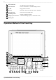
4 ──────────────────────────────────────────────────── 1 F1 to F10 key Serve to select setting items. 2 HELP key Provides on-line help. 3 CHAN key Causes the display to show the Channel screen which serves for making input channel settings. 4 DISP key Causes the display to show measurement and analysis results. 5 FILE key Causes the display to show the File screen which serves for reading, storing, etc. the waveform data etc. 6 TRIG key Causes the display to show the Trigger screen.
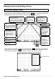
5 ──────────────────────────────────────────────────── Display Screen and Setting Screen Waveform display screen The screen shown below appears immediately after the power switch is turned on. The waveform display screen can also be displayed by pressing the red DISP key. The following explains the displayed items and the items that can be set in the waveform display screen.
6 ──────────────────────────────────────────────────── CH setting CH setting F9 F9 Input unit setting Trigger setting The following settings can be entered for each channel: Display ON/OFF Voltage axis range (vertical axis) setting Zero-position setting Display graph setting Coupling setting Magnification / compression of the vertical axis Low-path-filter setting The following settings can be entered for each channel.
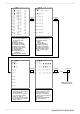
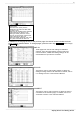
7 ──────────────────────────────────────────────────── Channel screen The channel screen can be displayed by pressing the CHAN key located on the left side of the unit. This screen is used to set units (analog input) and to enter logic input, display the settings for each channel, and to enter scaling settings, comments, and other detail settings. List Indicates the channel. Settings can be copied between channels. Indicates the unit type. Used to select waveform display ON/OFF.
8 ──────────────────────────────────────────────────── Options page Selection of the probe pressuredistribution ratio when the 9665, 9666, or 9322 is used Setting of the antialiasing filter (enabled when used with the 8953-10 unit) Setting of details (reference contact, burnout) for temperature measurement when used with the 8954 unit Setting of details (threshold, hold, level, etc.
9 ──────────────────────────────────────────────────── Trigger screen The trigger screen can be displayed by pressing the TRIG key located on the left side of the unit. This screen is used to set the trigger for each channel. To switch the page between analog and logic, press the Page Switch key ( F3 function key). Analog trigger setting Trigger acceptance setting (single / repeat / auto) When set to "Single," one trigger is accepted.
10 ──────────────────────────────────────────────────── Status screen The status screen can be displayed by pressing the STATUS key located on the left side of the unit. This screen is used to enter basic waveform data-acquisition settings, memory allocation settings, and calculation settings. STATUS Used to set the time axis (horizontal axis). The sampling speed changes automatically. Used to set recording length. The recording time changes automatically.
11 ──────────────────────────────────────────────────── System screen The system screen can be displayed by pressing the SYSTEM key located on the left side of the unit. To change pages, press the menu key ( F1 F2 function keys). The system screen is used to enter settings common to all functions; settings for printer, files, and communication; 8855 initial settings; and self-diagnosis settings. The following briefly describes each of these setting pages. SET UP (Refer to 9.
12 ──────────────────────────────────────────────────── INTERFACE (Refer to Chapter 11 "Communication Settings" in the Instruction Manual.) LAN settings FTP settings PC card settings (RS-232C, GP-IB, modem) PPP settings (transmission, reception, etc.) INITIALIZE (Refer to 9.5 "Initialize Screen" in the Quick Start Manual.) Clock setting Waveform data initialization System reset Menu control (display/hide setting) SELF CHECK (Refer to 9.6 "Self-check" in the Quick Start Manual.
13 ──────────────────────────────────────────────────── Measurement Method Operation flow Pre-measurement operations 1 What is the measurement target object? What is the voltage of the target object? Check the maximum input voltage. Check the maximum ground input voltage. 2 Connect the power cord to the 8855 unit. Confirm that the power-supply voltage is 100 VAC to 200 VAC. Confirm that the power-supply frequency is 50/60 Hz (sine wave). 3 Connect to the measurement target object.
14 ──────────────────────────────────────────────────── Simple measurement operations The following describes the simple operating procedures with a waveform input into Channel 1 (CH1) of the 8855 HiCORDER. (Example) Input of a sine wave of 1 kHz and 1 V, and observation of the waveform Procedure (1) Press the DISP key to display the waveform display screen. (2) Move the flashing cursor to the "Function" indication at the upper left corner of the screen, then press the F1 key and select "Memory.
15 ──────────────────────────────────────────────────── Measurement of instantaneous power interruption in a commercial power line DANGER To prevent electric shock and equipment damage, make sure each unit's maximum input voltage and maximum rated ground voltage (described in Chapter 2 "Installation and Preparation" in the Instruction Manual provided with the product) are not exceeded. 1.
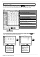
16 ──────────────────────────────────────────────────── 3. Setup Display Status screen Setting item Setting Time axis (Time/Div) 20 ms/DIV Recording length (Shot) 30DIV Channel screen Display mode (Format) Dual Graph CH1 GR1 CH2 GR2 CH3 GR2 CH1 Voltage CH2 Voltage CH3 3273 CH1 20 V CH2 2V CH3 1A Mode Range Trigger screen Trigger mode Single Pre-trigger 20% Kind CH1 In Parameter CH1 Lower (limit): -100.00 V Upper (limit): 100.00 V Filt. (Filter): 1.5 DIV 4.
17 ──────────────────────────────────────────────────── 2. Window display Move to "Format." (1) Separate the display of commercial power-supply waveforms from the display of other waveforms to prevent overlapping. Using the cursor keys, move the flashing cursor to "Format." Then, press the function key to set the "Format" to "DUAL." Press the function key corresponding to the setting displayed in the screen. Set to DUAL. Status screen Display the channel screen.
18 ──────────────────────────────────────────────────── 3. Channel setting Move to "Range" or "Mode." Press the function key corresponding to the setting displayed in the screen. Set to 3273. Set each range. Using the cursor keys, move the flashing cursor to "Range" or "Mode." Since CH1 receives a commercial 100-V power supply (approx. 141 Vp), press the function key to set the range (vertical axis) to "20 V/DIV.
19 ──────────────────────────────────────────────────── 4. Trigger setting Display the trigger screen. Move to "Type," "Parameter," "Trigger mode," and "Pre-trigger." Press the function key corresponding to the setting displayed in the screen. Set to "Single" and "20%." The following describes the trigger condition setting method. To activate the trigger at the time of instantaneous power outage, use "Window In trigger.
20 ──────────────────────────────────────────────────── 5. Starting measurement Display the display screen. Start measurement. (1) Press the DISP key to display the display screen. (2) Press the START key to begin measurement. When an instantaneous power outage occurs, the trigger is activated and a waveform is acquired. Until then, the unit stands by. The following shows an actual waveform obtained based on the conditions listed below.
21 ──────────────────────────────────────────────────── Measurement of the sensor output 1. Method Use the 8953-10 HIGH RESOLUTION UNIT to measure the output of the acceleration sensor. Observe the waveform of the effect caused by an impact applied to the subject board. 2. Connection Connect the sensor output (output from the amp that magnifies the sensor output in this example) to the input terminal of the 8953-10 HIGH RESOLUTION UNIT (CH1).
22 ──────────────────────────────────────────────────── 3. Setup Display Status screen Channel screen Setting item Setting Time axis (Time/Div) 1 ms/DIV Recording length (Shot) 1000DIV Range CH1 200 mV Scaling CH1 In decimals (ENG) Setting method (Scaling Kind) CH1 Set with 2 points (POINT) Trigger screen Input P1 - Scale P1 CH1 [2.000] - [5.000] Input P2 - Scale P2 CH1 [-2.000] - [-5.
23 ──────────────────────────────────────────────────── Display the channel screen. Move to "Range," "Scaling," "Scaling kind," "Input/ Scale," and "Unit." Press the function key corresponding to the setting displayed in the screen. 2. Channel setting (1) Press the CHAN key to display the channel screen. (2) Make sure CH1 is selected. Using the cursor keys, move the flashing cursor to "Range." If CH1 is not selected, press the F3 key to select CH1 before moving the cursor to "Range.
24 ──────────────────────────────────────────────────── Display the trigger screen. Move to "Kind," "Parameter," "Trigger Mode," and "Pre-Trigger." Press the function key corresponding to the setting displayed in the screen. 3. Trigger setting The following describes the procedure for setting trigger conditions. When there is a change from 0 V (0 G), the trigger is activated and waveform acquisition starts. (1) Press the TRIG key to display the trigger screen.
25 ──────────────────────────────────────────────────── 5. Starting measurement Display the display screen. Start measurement. Press the DISP key to display the display screen. Press the START key to begin measurement. When the START key is pressed, "Waiting for trigger" is displayed at the upper right corner of the screen. When "Waiting for trigger" is displayed, apply an impact to the subject board. The trigger is activated, and "Storing" is displayed at the upper right corner of the screen.
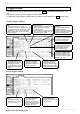
26 ──────────────────────────────────────────────────── 6. Analysis of waveforms Display the display screen. (1) Waveform zoom Using the cursor keys, move the flashing cursor to the location shown in the diagram. Using the F1 or F2 function key, magnify or compress the displayed waveform. To view the entire waveform on a single screen, press the F5 key. Move the flashing cursor. Use the F1 or F2 key to magnify or compress the waveform.
27 ──────────────────────────────────────────────────── (3) A-B cursors A-B cursors are used to read frequency and numerical values such as maximum values. When the A.B CSR key is pressed, the red LED lights up and the GUI for A-B cursor settings appears. Select the type of cursor, ON/OFF of A-B cursors, and movement for reading a numerical value. < Key point > The waveform display screen can be switched between 30 DIV and 20 DIV by pressing the DISP key.
28 ──────────────────────────────────────────────────── External Memory Devices The following memory devices and data recording methods can be used with the 8855. By selecting a device or method, data can be saved in the specified media. Data saved on any of these media in the 8855 recording format can be loaded into the 8855 for display and analysis. 1. Internal memory devices FD drive (floppy disk) MO drive (MO disc) HD drive (hard disk) 2.
29 ──────────────────────────────────────────────────── Selection of recording media (1) Press the FILE key. The file screen is displayed. (2) Press the media c hange F1 key. (3) Press the function key, and select a media for file saving and loading operations from among "FD," "PC CARD," "MO/HDD," "MO (EXT)," or "RAM." In this example, "Internal MO/HDD" is selected. Display the file screen. Press the F1 key.
30 ──────────────────────────────────────────────────── Storage of measurement data Select a file save format. Displays the execution command. Set the processing to be executed if the entered file name already exists. Specify the range of data to be saved. Displays the information of the file to be saved. Enter a name for the file to be saved. When data is saved as text, set a thinning rate. Specify the channel to be saved.
31 ──────────────────────────────────────────────────── (5) Enter a name (file name) for the data to be saved. Move the flashing cursor to "Save Name." Press the input F1 key to display the character input screen. Enter a file name. Regarding the input method, refer to "5.3.3 Character Entry Procedure" in the 8855 Instruction Manual. F1 input Character input screen (6) Specify the method of processing to be executed if the entered file name already exists.
32 ──────────────────────────────────────────────────── Reading measurement data Select a data reading method. Displays the execution command. Displays the information of the file to be loaded. When reading a settings file, specify whether settings other than channel settings are to be loaded. Specify the channel to be loaded. (1) Display the file screen, and select the media used to load data (refer to "Selection of recording media"). (2) Press the load F3 key. F3 load Move to "Loading type.
33 ──────────────────────────────────────────────────── (4) Setting of a basic loading operation (for loading of settings files only) Move the flashing cursor to "Basic Load," and select a loading method. Move to the item to be set. Press the function key corresponding to the setting displayed in the screen. None Does not load settings other than channel settings. All main-unit settings other than channel settings are retained. Load Loads settings other than channel settings. Loads all setting data.
34 ──────────────────────────────────────────────────── Automatic saving of measurement data After measurement, data can be automatically saved in a specified media. For details, see 9.3.1 "Setting the Auto Save Function" in the 8855 Quick Start Manual. Press several times to select "FILE SAVE." (1) Press the SYSTEM key several times, and select "FILE SAVE" in the menu screen.
35 ──────────────────────────────────────────────────── Starts measurement Stops measurement (9) When saving data in text form, set a data thinning rate. Move the flashing cursor to "Save Thin," and select a thinning rate. (10) Start measurement. Press the START key to start measurement. After data of the set recording length is obtained, the data is automatically saved. To stop the measurement or auto-save operation, press the STOP key. To forcibly stop the operation, press the STOP key twice.
36 ──────────────────────────────────────────────────── Useful Information 1. About the function keys (1) Memory function Stores A/D-converted data in the memory for each sampling operation. Changing the time axis also alters the sampling frequency. (2) Recorder function The sampling frequency is fixed. Because changing the sampling frequency does not alter the time axis, measurement at a fast sampling speed is possible even with a slow time axis.
37 ──────────────────────────────────────────────────── 5. About the voltage axis and resolution The resolution of the 8950, 8951, and 8952 with a voltage axis of 1 DIV is 100 (100 LSB). The full scale of the screen is 20 DIV, so the resolution is 2000 LSB (at a voltage axis magnification rate of 1). (Example) With a voltage axis of 5 V/DIV, the minimum resolution is as follows: 5 V / 100 = 50 mV. The resolution of the 8953-10 with a voltage axis of 1 DIV is 1600 (1600 LSB).
HIOKI 8855 MEMORY HiCORDER GUIDE BOOK Publication date: July 2002 Edition 1 Edited and published by HIOKI E.E. CORPORATION Technical Support Section All inquiries to Sales and Marketing International Department 81 Koizumi, Ueda, Nagano, 386-1192, Japan TEL: +81-268-28-0562 / FAX: +81-268-28-0568 E-mail: os-com@hioki.co.jp URL http://www.hioki.co.
HEAD OFFICE 81 Koizumi, Ueda, Nagano 386-1192, Japan TEL +81-268-28-0562 / FAX +81-268-28-0568 E-mail: os-com@hioki.co.