
Data Sheet

3
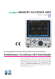
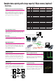
20 MS/s high-speed sampling for all channels using isolated input
- Functions -
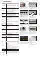
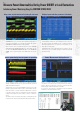
The trigger function allows you to set various conditions
for input waveforms in order to capture waveform
anomalies. It is convenient for analyzing the causes of
anomalies, since a pretrigger can be set, enabling you to
observe waveforms before starting the trigger search. In
contrast to above, this function allows you to search for
and display anomalous waveforms in captured data using
the same criteria used for the trigger function during
measurement. If triggers cannot be set during measurement
because you do not know what sort of waveforms will be
displayed, you can search for anomalies using the trigger
search function once all of the data has been captured.
Using the trigger function during data capture and the trigger
search function after data has been captured
This mark
indicates the
trigger point.
Three-phase inverter output system
(Since the electric potential of the emitter is different for each phase, floating measurement is indispensable.)
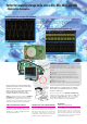
Measuring the surge noise for power lines (using the DIFFERENTIAL PROBE 9322 in AC mode)
If you select AC as the output mode, the signal connected to AC is divided to 1/1000 inside the probe
and output. Because the frequency range can be set between 1 kHz and 10 MHz, the output waveform is
displayed only when a voltage signal that includes a high waveform component is input, such as surge noise
superimposed on a 50/60 Hz commercial power line. Therefore, the 8855 can be used primarily to detect
noise, as well as to measure the height of waves.
Rectified RMS voltages can be output (using the DIFFERENTIAL PROBE 9322 in RMS mode)
When RMS is selected as the output mode, the input signal voltage is divided to 1/1000, then true RMS
value rectification is performed, and the DC voltage output. RMS value rectification is performed by
analog circuitry, and because the bandwidth extends from 40 Hz to 100 kHz, signals that include harmonic
components can be accurately converted to RMS values not only for 50/60 Hz commercial power lines, but
for other waveforms containing harmonics, such as inverter output waveforms.
Use the 8855 to capture power line noise:
In order to capture events such as impulse noise caused by lightning strikes and the opening and closing of solenoids,
and voltage surge noise (voltage swells) caused by switching power lines with heavy loads, the 8855 comes equipped
with window out trigger and glitch trigger functions.
Use the 8855 to capture instantaneous power outages on power lines:
Using the window out trigger and trigger filter functions, you can capture instantaneous power outages due to events
such as lightning strikes and breaker trippage due to short circuits.
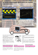
When measuring the difference in electrical potential
between two signals that have a large overlapping common
mode voltage, electric shock may result if you are not
using a measurement unit with completely insulated input
channels like the MEMORY HiCORDER 8855. Further,
when measuring signals with a superimposed common
mode voltage that includes high frequency components,
such as inverter control and switching power circuit
signals, the frequency characteristics for the common
mode removal comparison of the insulated area greatly
affect the measurement results. For example, when using
the ANALOG UNIT 8950, the peak-to-peak value for all
waveform data can be measured or displayed in a range
configuration of up to 280 V RMS using the memory
function. If you want to measure voltages that exceed 280
V, you can use the optional DIFFERENTIAL PROBE
9322 to measure voltages up to 2000 V DC or 1000 V AC.
Because a maximum voltage to ground of 1500 V AC/DC
(CAT II) is possible, you can measure the common mode
voltage for larger systems than before.
Can I use the 8855 to measure high voltages,
such as inverter output ?
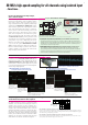
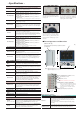
Observation of distorted current is possible when using the 8855
in combination with the VOLTAGE/CURRENT UNIT 8951 and
a clamp-on probe or clamp-on sensor. Especially when using the
CLAMP ON PROBEs 3273
-50, 3274, 3275, or 3276, you can
accurately observe current waveforms ranging from very small
to very large with a highly linear response for current frequencies
from DC voltage to high frequencies.
Can I observe distorted current, such as that of inverter output ?
■
CLAMP ON PROBEs 3273-50/3274/3275/3276
(when measuring very low current with high S/N characteristics)
Actual measurement example for inverter current
using the 8855 in combination with the 3274
■
CLAMP ON PROBEs 3273-50/3274/3275/3276
(rectangular waveform response characteristic)
3274
100 kHz rectangular
waveform 400 mAp-p
(oscilloscope bandwidth
100 MHz)
3273-50
1 MHz rectangular
waveform 200
mAp-p (oscilloscope
bandwidth 400 MHz)
3275
10 kHz rectangular waveform, 400 mAp-p
(oscilloscope bandwidth 20 MHz)
3275
1 kHz sine wave, 50 mAp-p
(oscilloscope bandwidth 20 MHz)
3274
1 kHz sine wave 50
mAp-p (oscilloscope
bandwidth 100 MHz)
3273-50
1 kHz sine
wave 10 mAp-p
(oscilloscope
bandwidth 20 MHz
)
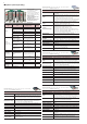
Using the DIFFERENTIAL PROBE 9322
The POWER CORD 9328
(when connected to the power plug
of the 9322 and the 12-V output
connection of the input unit)