
Data Sheet

11
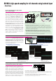
This function works with the single-phase two-wire,
single-phase three-wire, three-phase three-wire,
three-phase four-wire and DC connection modes,
making it possible to measure systems ranging
from four single-phase two-wire systems, to a
combination of one three-phase four wire system
+ one single-phase two-wire system. Calculations
can be performed on partial waveforms selected
for all wavefor ms in storage by using the A-B
cursors, and results can be displayed in a single
screen. Nume r ic results can be displaye d as
overlays in the waveform screens.
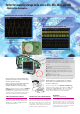
Power monitor function
(installed as an option)
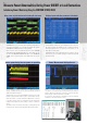
Instantaneous power waveform display
(power monitor function)
Using this function, you can do calculations using
voltage and current waveforms stored in memory,
and display th e r e s u l t s a s voltage, c u r rent,
or p ower trend graphs. This e n a b les yo u to
perform detailed analyses on the transient power
segments, such as when a device is powered on
or during load fluctuations.
Trend graph display
(power monitor function)
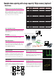
Power monitor specifications and options
FUNCTION UP DISK 9549
Power moniter function add in to
the MEMORY HiCORDER 8855
MEMORY HiCORDER 8855 (main unit + FUNCTION UP DISK 9549 )
Sample configuration for use with single-phase 2-wire systems
(8855 + one each 9549, 8950, and 8951) + (one each 9197 and 3275)
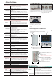
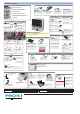
Various input modules
User-installable in any combination by insertion into
the instrument.
Note: Input cords are not provided. Please purchase
the appropriate input cord for the probe type and
application separately.
ANALOG UNIT 8950
VOLTAGE/CURRENT UNIT 8951
DC/RMS UNIT 8952
HIGH RESOLUTION UNIT 8953-10
Cannot be used for power calculations
VOLTAGE/TEMP UNIT 8954
Cannot be used for power calculations
F/V UNIT 8955
Cannot be used for power calculations
CONNECTION CORD
9197
For high voltage (up to 500 V)
Voltage input for
100/200 V systems
For Input Voltages
Esceeding 280 V rms
POWER CORD 9328
Connects to the DIFFERENTIAL
PROBE 9322 and the input unit.
DIFFERENTIAL PROBE 9322
For input up to 2 kV DC or 1
kV AC. Requires one POWER
CORD 9328 for each probe.
CONNECTION CORD
9198
For low voltage (up to 300 V)
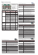
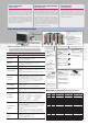
■ Waveform recording lengths for power calculations
(When the optional recording length is set) The recording lengths are longer than when using the fixed
recording length. The number of channels in use does not affect the recording length.
Power monitor function
(optional, sold separately, for use with the 9549)
Measurement functions
Power monitor
Input modules that
can be used
Voltage: ANALOG UNIIT 8950, DC/RMS UNIT 8952
Current: VOLTAGE/CURRENT UNIT 8951
(can be used with a clamp-on probe)
Time axis
5 µs to 5 s/div
(100 samples/div)
19 settings; external sampling
(1 sample/
div, desired setting)
; time axis zoom ×2 to ×10, 3 settings;
compression 1/2 to 1/10,000, 12 settings
Sampling period
1/100 of time axis ranges
(minimum sampling cycle of 50 ns)
Recording length
Fixed setting: 30 to 10,000 div, 20,000*
1
div, 50,000*
2
div, 100,000*
2
div
Desired setting: 1 to 10,000 div (standard), 1 to 40,000*
1
div, 1 to
160,000*
2
div
*1
When using 128 MW expanded memory, *2 When using 512 MW expanded
memory, the maximum recording length depends on the number of channels being
used.
Calculation
accuracy
Using the CLAMP ON PROBE 3273-50, 3274, 3275, or 3276 : ±2.0 % rdg.*
3
Using the UNIVERSAL CLAMP ON CT 9277, 9278, or 9279 : ±2.5 % rdg.*
3
Using the CLAMP ON SENSOR 9270 or 9272
(20 A range)
: ±3.5 % rdg.*
3
Using the CLAMP ON SENSOR 9271 or 9272
(200 A range)
: ±2.0 % rdg.*
3
*3 Input sine wave (50 % f.s.), power factor = 1, 55 Hz, single-phase 2-wire, calculation
(11 waveforms), input coupling AC, filter: OFF, after offset adjustment has been
performed for the clamp-on probe
Screen display
Storage waveform
(analog, logic)
, waveform calculation, parameter
value, cursor read value
screen/print settings: 1, 2, 4, or 8 screens can be displayed
Other functions
Recording line settings
(12 colors)
, overlay function, waveform scrolling,
zoom function, logging function, variable display function, waveform
judgment
Power value
calculations
Calculation channels: max. 4 fixed probes, voltage channels 1 to 4, current channels 5 to 8
Numerical calculations: displays each voltage and current as a single block
U rms : RMS voltage, I rms : RMS current, U mn : average voltage,
I mn : average current, U dc : simple average voltage, I dc : simple average current,
U pk± : peak voltage, I pk± : peak current, Uf : voltage frequency,
If : current frequency, P : effective power, S : apparent power,
Q : reactive power, λ : power factor, φ : phase
Calculation area: All data stored in memory, area between the A and B cursors
Power waveform
calculations
Calculation channels: max. 4 fixed probes, voltage channels 1 to 4, current channels 5 to 8
Display channels: displays a total of 16 channels on the screen, including 8 input waveform
and 8 calculation waveform channels.
Waveform calculation: instantaneous power waveforms
(the time axis for the real-time display
is 10ms/div slower)
, trend graph of effective power points that cross zero
(after data storage
is complete)
, trend graph of voltage/current
(RMS value fluctuation)
Calculation memory:
With standard memory (32 MW): up to 10,000 div regardless of the number of channels
With 128 MW expanded memory: up to 40,000 div regardless of the number of channels
With 512 MW expanded memory: up to 160,000 div regardless of the number of channels
Triggers
Trigger types: level, window in, window out, period, glitch, event, logic
pattern
(conforms to specifications for the 8855)
Zero cross: search using software
Zero cross filter: OFF, Narrow, Wide, Inverter
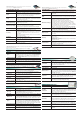
Time axis
Sampling
period
With standard memory capacity
(32 MW) Maximum recording
length of 10,000 divisions
With standard memory capacity
(128 MW) Maximum recording
length of 40,000 divisions
With standard memory capacity
(512 MW) Maximum recording
length of 160,000 divisions
5μs/DIV 50ns 0.05s 0.2s 0.8s
10μs/DIV 100ns 0.1s 0.4s 1.6s
20μs/DIV 200ns 0.2s 0.8s 3.2s
50μs/DIV 500ns 0.5s 2s 8s
100μs/DIV 1μs 1s 4s 16s
200μs/DIV 2μs 2s 8s 32s
500μs/DIV 5μs 5s 20s 1m 20s
1ms/DIV 10μs 10s 40s 2m 40s
2ms/DIV 20μs 20s 1m 20s 5m 20s
5ms/DIV 50μs 50s 3m 20s 13m 20s
10ms/DIV 100μs 1m 40s 6m 40s 26m 40s
20ms/DIV 200μs 3m 20s 13m 20s 53m 20s
50ms/DIV 500μs 8m 20s 33m 20s 2h 13m 20s
100ms/DIV 1ms 16m 40s 1h 6m 40s 4h 26m 40s
200ms/DIV 2ms 33m 20s 2h 13m 20s 8h 53m 20s
500ms/DIV 5ms 1h 23m 20s 5h 33m 20s 22h 13m 20s
1s/DIV 10ms 2h 46m 40s 11h 6m 40s 1d 20h 26m 40s
2s/DIV 20ms 5h 33m 20s 22h 13m 20s 3d 16h 53m 20s
5s/DIV 50ms 13h 53m 20s 55h 33m 20s 9d 6h 13m 20s
This function multiplies captured voltage and current
waveforms and displays the result as an instantaneous
power waveform. (Display in real-time is possible through
hardware integration processing for speed ranges up to
10 ms/DIV. For faster ranges, power waveform display
is calculated after first storing waveforms in memory.)
Power waveform display allows up to 8 waveforms to be
displayed in addition to voltage and current waveforms,
and a total of up to 16 waveforms can be displayed
simultaneously (8 voltage/current channels, and 8
power waveforms). Using the appropriate input units,
values such as temperature and frequency can be
simultaneously observed on channels for which power
calculations are not being performed.
CONVERSION CABLE 9318
(to connect the 9272 - 9279 and
the 8951)
VOLTAGE/CURRENT UNIT 8951
UNIVERSAL CLAMP ON CT
9277
Observe waveforms from DC to distorted AC.
DC to 100kHz response, input 20A / output
2V AC
UNIVERSAL CLAMP ON CT
9278
Observe waveforms from DC to distorted AC.
DC to 100kHz response, input 200A / output
2V AC
UNIVERSAL CLAMP ON CT
9279
Observe waveforms from DC to distorted AC.
DC to 20kHz response, input 500A / output
2V AC
Current measurement * Band width DC to 100 kHz class
CLAMP ON SENSOR
9272
-10
Enables observation of AC current
waveforms. Input: 1 to 100kHz, selectable
20 and 200A rms ranges, 2V AC output
Not CE marked
CONVERSION CABLE 9318
to connect the 9272 to 9279 and the 8951
3273-50
3276
3274
3275
CLAMP ON PROBE 3273-50
DC to 50MHz wideband response,
mA-class current up to 30A rms
CLAMP ON PROBE 3274
DC to 10MHz wideband response,
mA-class current up to 150A rms
CLAMP ON PROBE 3275
DC to 2MHz wideband response,
mA-class current up to 500A rms
CLAMP ON PROBE 3276
DC to 100MHz wideband response,
mA-class current up to 30A rms
Note: The 3270 series can be directly
connected to the VOLTAGA/
CURRENT UNIT 8951.
VOLTAGE/CURRENT UNIT 8951
Current measurement *
Band width DC to 100 MHz class