
Data Sheet


10
Measure Power Abnormalities During Power ON/OFF or Load Fluctuations
Introducing Power Monitoring Using the FUNCTION UP DISK 9549
By installing the power monitor function in the MEMORY
HiCORDER 8855, you can monitor power transient waveforms and
view power trend graphs. Use of this function requires the optional
FUNCTION UP DISK 9549, which is sold separately.
Input units that can be used with this function are the ANALOG
UNIT 8950 and the DC/RMS UNIT 8952. For current input, you can
use either the VOLTAGE/CURRENT UNIT 8951, or the CLAMP ON
PROBE 3273
-50/3274/3275/3276. (The 9270 Series can also be
used.)
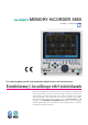
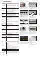
Calculated power results for all acquired waveforms or the span
selected with the A-B cursors can be displayed on the screen as a
list. A full 4 channels are available for each of voltage and current,
allowing measurement of one 3-phase, 3-wire system, or one
single-phase, 2-wire system.
Calculated results can be displayed either as numerics only (as
shown above), or as a numeric overlay in a waveform screen like
that shown at left.
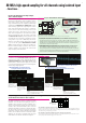
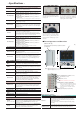
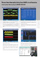
Voltage, current, and power waveforms on the secondary side of an inverter
Display of power and other parameters (calculated)
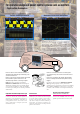
You can display a variety of waveforms accompanying inverter
startup, including transient (excess) power waveforms and trend
graphs (fluctuation waveforms).
Together with its noise-resistant CMRR characteristic, the high
floating voltage maintained by the 8855's isolated input assures
stable observation of voltage waveforms. Observation of current
is possible using the 8855 in combination with the appropriate
voltage/current input unit and a clamp-on probe or clamp-on
sensor.
This makes it easy to measure power surges occurring when power
is turned on that cannot be measured with ordinary power meters.
There is no need to set up complicated operations, such as
calculations for waveform processing involving the memory
function. All that is needed is to select the connect mode and a
waveform type of either instantaneous or variable.
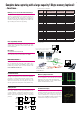
A connection check function is provided to help you determine
whether the connection method is correct.
Excess power during inverter power-on operation Power Measurement Settings Screen