
User Manual


506
────────────────────────────────────────────────────
21.3 Reference
────────────────────────────────────────────────────
S=
n
l di l ・h
Σ
i=1
S
:
Area value
n
:
number of data samples
di
:
i-th data of the source channel
h=Δt
:
sampling period
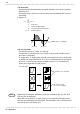
A cursor
B cursor
Shaded area is calculated
X-Y waveform
Shaded area is calculated
No enclosed range,
Line area is calculated
NOTE
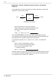
(13) Area value
・Calculates the area bordered by the signal waveform and the zero position
(potential 0 V).
・If the A/B cursors (vertical, trace) are used, the area between the cursors is
calculated.
【 Equation 】
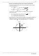
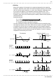
(14) X-Y area value
・Calculates the area (V
2
) after X-Y plotting.
・The waveform is plotted on the X-Y screen, and the area enclosed by the
plot lines is calculated.
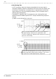
・In single, dual, or quad screen, the A/B cursors (vertical, trace) can be used
to specify the range (see Section 11.2.) for X-Y plotting and area calculation.
・On the X-Y screen of the memory recorder function, it is not possible to
specify the range with the A/B cursors.
・ Depending on the signal waveform, values for parameters (8), (9), (10), and
(11) may not be displayed.
・ When the scaling function is used, scaling is first applied to waveform data,
and then the parameters are calculated. The parameter unit is determined by
the scaling unit ( see Section 9.7).