
User Manual


14
────────────────────────────────────────────────────
2.4 Connection of the Input Unit
────────────────────────────────────────────────────
2
.4.1 8936 ANALOG UNIT / 8938 FFT ANALOG UNIT
WARNIN
G
・Never connect the probe to the 8826 while the probe is already
connected to the measurement object. Otherwise there is a risk of
electric shock.
・Be sure to use the input cord specified by HIOKI for 8826.
An insulated BNC is used to prevent electric shock.
Note that using a metal BNC may run the risk of electric shock, since
the input L-terminal and metal part of the BNC connector have the same
potential.
CAUTIO
N
・When disconnecting the BNC connector, be sure to release the lock before
pulling off the connector. Forcibly pulling the connector without releasing the
lock, or pulling on the cable, can damage the connector.
・Using an input cord other than that specified by HIOKI may damage the BNC
connector or result in measurement errors due to contact failure.
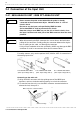
9197 CONNECTION CORD
(Max. input voltage 500 V
)
9198 CONNECTION CORD
(Max. input voltage 300 V
)
9217 CONNECTION CORD
(Max. input voltage 300 V
)
Connector ridge
BNC connector counterclockwise
2
.4 Connection of the Input Unit
For safety reasons, only use the optional 9197, 9198 or 9127 for connection to
the analog input units.
Connecting to the main unit
(1) Align the BNC connector with the guide groove of the 8826 input
connector, and turn clockwise while pressing in to lock the connector.
(2) To remove from the unit, turn the BNC connector counterclockwise to
release the lock, then pull it.