
User Manual


306
────────────────────────────────────────────────────
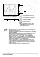
11.5 Input Level Monitor Function
────────────────────────────────────────────────────
All the logic displays are set to OFF, and th
e
instantaneous value of the input level is displaye
d
at the right of the screen (except for the X-Y
screen and FFT).
An instantaneous value for the analog channel i
s
displayed. In RMS recorder function, however, th
e
RMS value is not displayed.
【 The input level is not displayed on the screen
display range:
】
・・・The input level exceeds the upper limit.
・・・The input level exceeds the lower limit.
Screen: DISPLAY
Press the LEVEL.MON. key.
The CH.SET key can be used to select the
input channel while using the input level
monitor function.
Press the LEVEL MON. key once more to
terminate the function.
When the X-Y screen has been set, only
those channels assigned to graphs 1 to 4
are displayed.
Method
Method
【 Analog channel 】
【 Logic channel 】
Waveform level
Full span
・・・The input is stabilized at the HI level.
・・・The input varies drastically between the HI and
LOW levels.
・・・The input is stabilized at the LOW level.
・・・The display is disabled.
NOTE
1
1.5 Input Level Monitor Function
・The levels of all input waveforms can be monitored in real time.
・Levels are displayed separately for CH1 - CH32 and logical CH A - CH H.
・To select the input channel, use the CH.SET key. See Section 9.9.
・This function is available in all modes.
・The input levels can not be confirmed at FTT function.
・During measurement, the input levels can not be confirmed at RMS
function.
For the following channels, analog input level is not displayed:
・Channels where no unit is installed.
・A channel that deviates from the set active channel range(example: 5 ch or
subsequent channels when the number of set active channels is four).