
User Manual


284
────────────────────────────────────────────────────
10.8 Analog Trigger
────────────────────────────────────────────────────
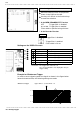
Move the flashing cursor to the position
shown in the figure.
Use the function keys to select the trigger
direction (slope).
:Enables triggering on the leading
edge.
:Enables triggering on the falling
edge.
Selection
Selection
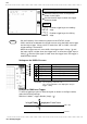
(3) Select the trigger direction (slope).
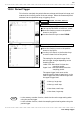
NOTE
Setting Item Setting Method
Trigger mode Function key
Trigger type Function key
Channel Function key, Jog (VALUE select key)
Trigger level Function key, Jog (VALUE select key)
Trigger slope Function key
Pre-trigger Function key
Restriction:The frequency cannot be set.
The selected window is not displayed in the pre-
trigger setting.
1
.00 V rm
s
0
Vrm
s
A
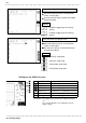
・Set the frequency of the measuring object on the STATUS screen.
・’AND’ cannot be set between the trigger sources using the RMS level trigger
and the logic trigger. When a shift is made from "OR" to "AND," the logic
trigger setting is turned OFF.
・When the trigger source is set to AND, the trigger slope is rising, (
) and
the input signal is higher than the trigger level, or when the trigger slope is
falling (
) and the input signal is lower than the trigger level, the trigger is
enabled upon startup.
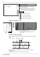
Settings on the DISPLAY screen
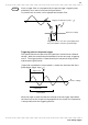
Example for RMS Level Trigger
To cause triggering at point A with the signal as shown in the figure below,
make the following settings.
RMS level: 1.000 V, trigger direction (slope): (
)