
User Manual


276
────────────────────────────────────────────────────
10.8 Analog Trigger
────────────────────────────────────────────────────
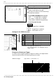
Move the flashing cursor to the position
shown in the figure on the left.
Use the JOG control or the function keys
to make the selection.
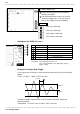
■ In the MEM, REC&MEM, FFT Function
OFF : Trigger filter is disabled
0.1 to 10.0 : Trigger filter is enabled.
Filter width is specified using divisions.
■ In the Recorder Function
:Trigger filter is disabled.
:Trigger filter is enabled.
Filter width is 10 ms.
Selection
Selection
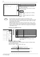
(3) Set the trigger filter
Setting Item Setting Method
Trigger mode Function key
Trigger type Function key
Channel Function key, Jog (VALUE select key)
Upper level Function key, Jog (VALUE select key)
Lower slope Function key, Jog (VALUE select key)
Pre-trigger Function key, Jog (VALUE select key)
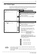
Restriction:The trigger filter cannot be set.
The selected window is not displayed in the pre-
trigger setting.
1
V
-
1V
0
V
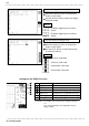
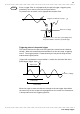
Window-out trigger Upper limit : 1 V, lower limit: -1 V
Settings on the DISPLAY screen
Example for Window-out Trigger
In order to cause triggering when the signal as shown in the figure below
leaves the hatched area, the following settings are made: