
User Manual


272
────────────────────────────────────────────────────
10.8 Analog Trigger
────────────────────────────────────────────────────
1
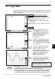
0.8.1 Level Trigger ( MEM and REC only )
T
rigger leve
l
T
rigger leve
l
[
Upward trigger direction (slope : )
]
[
Downward trigger direction (slope : )
]
I
nput waveform
T
rigger leve
l
F
ilter widt
h
T
rigger poin
t
T
riggering does not occur here
[
Rising trigger slope :
]
・Triggering occurs when the input signal crosses the preset trigger level
(voltage) with the preset trigger slope (
, ).
・When a trigger filter is used, triggering occurs only within the filter width.
This is useful to exclude noise.
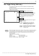
■
Trigger Filter
・Triggering occurs when the trigger conditions are met within the filter
width.
・This is useful to prevent spurious triggering by noise.
・The filter width is specified by the number of divisions of the memory
recorder function and FFT function, while it is fixed to 10 ms, which is
enabled and disabled using the ON/OFF keys, for the recorder function.