
User Manual


201
────────────────────────────────────────────────────
9.3 Setting the CHANNEL1 Screen
────────────────────────────────────────────────────
9
.3.5 Setting the Magnification/Compression Ratio Along the
Voltage Axis
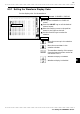
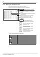
Screen: CHANNEL1, DISPLAY
Call up the CHANNEL1 or DISPLAY
screen.
Use the CH.SET key to display the desired
channel screen.
Move the flashing cursor to the position
shown in the figure on the left.
Use the function keys to make the
selection.
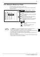
Method
Method
:Move the arrow up in the selection
window.
:Move the arrow down in the
selection window.
Selection
Selection
Flashing curso
r
NOTE
Format Display Size Magnification/
compression
Normal Wide
Single, X-Y single screen
20 DIV 24 DIV ×1/2, ×1, ×2, ×5, ×10
2, 4, 8, 16, X-Y4 screen
10 DIV 12 DIV ×1/4, ×1/2,×1, ×2.5, ×5
・Specifies the magnification/compression ratio for each channel to be used for
display and recording.
・Performs magnification/compression using the center of the screen as
reference.
・The measurable area for each voltage range is about ±1.25 times the full-
scale voltage axis. The display area on the waveform screen depends on the
magnification and compression settings, but the measurable area is not
affected. So even if seemingly displayable on the screen, any part of a
waveform that exceeds the measurable area of the voltage range cannot be
read.
・Magnification/compression along the measurement range is performed using
the center of the screen as reference, if the Magnification/compression ratio
is changed.
・Depends on display format, magnification/compression ratio is changed as
below: