
Installation Sheet

start here
commencez ici
empezar aquí
Assembly Instructions
Item No: 4669OB-CL
Les Instructions D’assemblage
Numéro d’article: 4669OB-CL
Instrucciones De Montaje
Número del artículo: 4669OB-CL
LIGHTING
HINKLEY
English Spanish
French
HINKLEY LIGHTING 33000 Pin Oak Parkway, Avon Lake, OH 44012 800.446.5539 / 440.653.5500 hinkleylighting.com
1. Find a clear area in which you can work.
2. Unpack fixture and glass from carton.
3. Carefully review instructions prior to assembly.
1. Encontrar un área clara en la que se puede trabajar.
2. Desembale xture fi y el vidrio de la caja.
3. Revise cuidadosamente las instrucciones antes del montaje.
1. Trouvez un endroit clair dans lequel vous pouvez travailler.
2. Déballez fi xture et de verre du carton.
3. Examinez attentivement les instructions avant l'assemblage.
SAFETY WARNING: READ WIRING AND GROUNDING INSTRUC-
TIONS (I.S. 18) AND ANY ADDITIONAL DIRECTIONS. TURN
POWER SUPPLY OFF DURING INSTALLATION. IF NEW WIRING IS
REQUIRED, CONSULT A QUALIFIED ELECTRICIAN OR LOCAL
AUTHORITIES FOR CODE REQUIREMENTS.
Make electrical connections from supply wire to fixture lead wires.
Refer to instruction sheet (I.S. 18) and follow all instructions to make
all necessary wiring connections. Then refer back to this sheet to
complete installation of this fixture.
ADVERTENCIA DE SEGURIDAD: CABLEADO DE LEER Y
INSTRUCCIONES DE CONEXIÓN A TIERRA (SI 18), E
INSTRUCCIONES ADICIONALES. VUELTA DE ALIMENTACIÓN
DURANTE LA INSTALACIÓN. SI SE REQUIERE UN NUEVO
CABLEADO, CONSULTE A UN ELECTRICISTA O AUTORI-
DADES LOCALES PARA REQUISITOS DEL CÓDIGO.
AVERTISSEMENT DE SÉCURITÉ: CÂBLAGE LIRE ET MISE A LA
TERRE (IS 18) ET TOUTE AUTRE INSTRUCTION. COUPER
L'ALIMENTATION PENDANT L'INSTALLATION. SI DE
NOUVELLES CÂBLAGE NE EST NÉCESSAIRE, CONSULTER UN
ÉLECTRICIEN QUALIFIÉ OU LES AUTORITÉS LOCALES LES
EXIGENCES DES CODES.
Haga las conexiones eléctricas del cable para suministrar cables
conductores de luz. Consulte la hoja de instrucciones (IS 18) y siga
todas las instrucciones para hacer todas las conexiones necesar-
ias. Luego vuelva a esta hoja para completar la instalación de este
accesorio.
Faire les raccordements électriques des fils fils conducteurs
d'alimentation du luminaire. Reportez-vous à la fiche d'instruction (IS
18) et suivez toutes les instructions de faire tous les raccordements
nécessaires. Puis revenez consulter cette fiche pour terminer
l'installation de este luminaire.
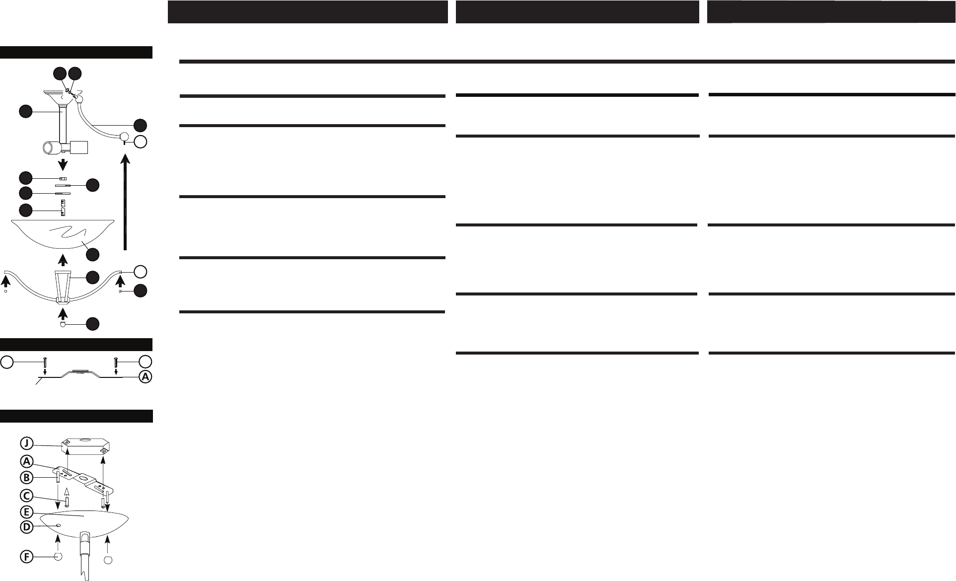
Drawing 3 - Fixture Mounting
Drawing 2 - Strap Detail
B
(side view)
gull wing
bracket
B
1
2
3
4
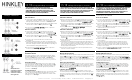
Drawing 1 - Fixture Assembly
12
11
H
G
9
7
6
8
10
5
1. To assemble main body, attach arms (3) to fixture column assembly (4)
using lock washer (2) and hex nut (1) - see Drawing 1.
1. Para montar el cuerpo principal, se unen los brazos (3) a
conjunto de la columna xture fi (4) utilizando la arandela de
seguridad (2) y la tuerca hexagonal (1) - ver Dibujo 1.
1. Pour assembler corps principal, attachent les bras (3) à l'ensem-
ble de colonne fi xture (4) à l'aide de la rondelle de blocage (2) et
l'écrou hexagonal (1) - voir schéma 1.
1. Prepare mounting strap (A) for installation by threading two screws (B)
provided into back of gull wing bracket of gem strap (A) - see Drawing 2.
• Be sure the holes into which the screws are threaded match the
spacing of holes (D)in the canopy (E) - see Drawings 2 and 3.
2. Install mounting strap (A) to junction box (J), using the two 1” screws
(C) not provided.
1. Preparar la correa de montaje (A) para la instalación enroscando
dos tornillos (B) previstas en la parte posterior del soporte de ala
de gaviota de la correa de la gema (A) - ver dibujo 2.
• Asegúrese de que los agujeros en los que los tornillos son de
rosca partido el espaciamiento de agujeros (D) en el dosel (E) - ver
dibujos 2 y 3.
2. Instale la correa de montaje (A) a la caja de conexiones (J), con
los dos tornillos de 25,mm (C) no previstos.
1. Préparer la sangle de fixation (A) pour l'installation en enfilant
deux vis (B) fournies à l'arrière du support d'aile de mouette de la
sangle de bijou (A) - voir Dessin 2.
• Assurez-vous que les trous dans lesquels les vis sont enfilés
match de l'espacement des trous (D) dans la canopée (E) - voir
dessins 2 et 3.
2. Installez la sangle de fixation (A) à la boîte de jonction (J), en
utilisant les deux vis de 25mm (C) ne sont pas fournis.
1. Prior to installing glass, fixture can now be lamped.
2. To install glass, set glass (6) onto bottom assembly (7) - see Drawing 1.
3. Attach finial (8) to end of nipple (5).
4. Slip nipple (5) through center hole in assembly (7) and glass (6).
5. Slip rubber washer (10) and metal washer (11) onto nipple (5).
6. Thread nut (12) onto end of nipple (5) and tighten.Note: Over tighten-
ing may cause damage to glass.
7. Line up the holes on the bottom assembly (7) arms (G) with the
threaded stud (H) extending out from end of arm (3).
8. Thread ball knob (9) onto end of stud (H).
1. Antes de instalar el vidrio, la luminaria se puede ahora lamped.
2. Para instalar vidrio, vidrio set (6) sobre el montaje inferior (7) -
ver Dibujo 1.
3. Coloque nial fi (8) hasta el final de la boquilla (5).
4. pezón El resbalón (5) a través del orificio central de montaje (7)
y vidrio (6).
Arandela 5. El resbalón goma (10) y la arandela de metal (11) en el
niple (5).
6. tuerca de hilo de rosca (12) en el extremo del pezón (5) y
tighten.Note: Apretar demasiado puede causar daños en vidrio.
7. Alinee los agujeros en la parte inferior de montaje (7) brazos (G)
con el espárrago roscado (H) que se extiende desde el extremo del
brazo (3).
Perilla 8. hilo de rosca bola (9) en el extremo del perno (H).
1. Avant d'installer le verre, le luminaire peut maintenant être
lamped.
2. Pour installer verre, set (6) sur l'assemblage de fond (7) - voir
schéma 1.
3. Fixez fi nial (8) à la fin du mamelon (5).
4. Glissez mamelon (5) dans le trou central dans l'assemblage (7) et
le verre (6).
5. Slip rondelle en caoutchouc (10) et la rondelle métallique (11) sur
le mamelon (5).
6. écrou de fil (12) sur l'extrémité de l'embout (5) et tighten.Note: Un
serrage excessif peut causer des dommages au verre.
7. Alignez les trous sur l'ensemble de fond (7) bras (G) avec la tige
filetée (H) se prolongeant à partir extrémité du bras (3).
8. Discussion balle bouton (9) sur l'extrémité du goujon (H).