
Instructions


Network Bullet Camera·Quick Start Guide
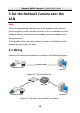
10
10
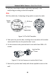
1 Appearance Description
This network bullet camera appearance is shown as the figures
below.
D
C
1
2
V
I
N
5
6
1
2
4
3
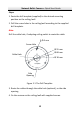
Network Bullet Camera Overview Figure 1-1
Description Table 1-1
No.
Description
1
Lens
2
Front Cover
3
Back Cover
4
Fix Ring
5
Power Cord
6
Network Cable
Note:
For cameras support power over Ethernet (PoE), the power is passed
along with data on Ethernet cabling. And a switch supports PoE
function is required.