
User Manual
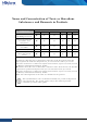

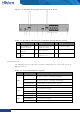
Table Of Contents
- Hillstone Hardware Reference Guide
- Name and Concentration of Toxic or Hazardous Substances and Elements in Products
- Preface
- Table of Contents
- List of Figures
- List of Tables
- Chapter 1 Introduction
- Chapter 2 Installation Preparations
- Chapter 3 Installation
- Chapter 4 Boot and Configuration
- Chapter 5 Troubleshooting
- Copyright Information
- FCC Statement:

Hillstone Hardware Reference Guide
Figure 1-2: SG-6000-E1100 (WLAN version) Back Panel
Table 1-2: Back Panel Description of SG-6000-E1100 (WLAN version)
No. Label No. Label No. Label
1
DC POWER: DC
power interface
4
SMA connectors for
WLAN antennas
7 Security keyhole
2
CLR: CLR
button
5 USB: USB port - -
3
CON: Console
port
6
e0/0 - e0/8: Gigabit
Ethernet port
- -
LED Indicators
The following table describes the meanings of LED indicators on the front panels of
Hillstone devices.
Table 1-3: Front Panel LED Descriptions
LED Color/Status Description
PWR
Green/Always
on
The device power is running normally.
Orange/Always
on
The device power is running abnormally.
Red/Always on Power failure so the system is down.
Off The device is powered off.
STA
Green/Always
on
The system is booting.
Green/Blinking The system is running normally.
Red/Always on The system has failed to boot or has an error.
ALM
Red/Always on The system is sending alarm(s).
Green/Blinking The system is waiting.
Orange/Blinking The system is using a trial license.
2
Chapter 1 Introduction
| Hillstone