
User's Manual

6
List of Figures | Hillstone
Hillstone Multi-core Security Appliance Installation Manual
List of Figures
Figure 1-1: SG-6000-G5150 Front Panel ..................................................................................................................... 3
Figure 1-2: SG-6000-G2120 Front Panel ..................................................................................................................... 4
Figure 1-3:SG-6000-M8860 Front Panel .................................................................................................................. 4
Figure 1-4:SG-6000-M7260 Front Panel .................................................................................................................. 5
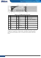
Figure 1-5: SG-6000-M3108 Front Panel .................................................................................................................... 6
Figure 1-6: SG-6000-M3100 Front Panel .................................................................................................................... 6
Figure 1-7: SG-6000-M1600 Front Panel .................................................................................................................... 7
Figure 1-8: Front Panel of SG-6000-E2800 and SG-6000-E2300 ................................................................................. 7
Figure 1-9: SG-6000-E1700 Front Panel ...................................................................................................................... 8
Figure 1-10: SG-6000-E1600 Front Panel .................................................................................................................... 8
Figure 1-11: Front Panel of SG-6000-E1100 (WLAN version) ..................................................................................... 9
Figure 1-12: Front Panel of SG-6000-E1100 (3G version) ........................................................................................... 9
Figure 1-13: Front Panel of SG-6000-E1100 (WLAN+3G version) ............................................................................. 10
Figure 1-14: SG-6000-G5150 Back Panel .................................................................................................................. 10
Figure 1-15: SG-6000-G2120 Back Panel .................................................................................................................. 11
Figure 1-16: SG-6000-M8860 Back Panel ................................................................................................................. 11
Figure 1-17: SG-6000-M7260 Back Panel ................................................................................................................. 11
Figure 1-18: SG-6000-M3108 Back Panel ................................................................................................................. 11
Figure 1-19: SG-6000-M3100 Back Panel ................................................................................................................. 12
Figure 1-20: SG-6000-M1600 Back Panel ................................................................................................................. 12
Figure 1-21: Back Panel of SG-6000-E2800, SG-6000-E2300, and SG-6000-E1700 .................................................. 12
Figure 1-22: SG-6000-E1600 Back Panel ................................................................................................................... 12
Figure 1-23: SG-6000-E1100 (WLAN version) Back Panel ......................................................................................... 13
Figure 1-24: SG-6000-E1100 (3G version) Back Panel .............................................................................................. 13
Figure 1-25: SG-6000-E1100 (WALN+3G version) Back Panel .................................................................................. 14
Figure 1-26: AC Power Module for SG-6000-G5150/M8860/M7260 ....................................................................... 26
Figure 1-27: DC Power Module for SG-6000-G5150/M8860 /M7260 ...................................................................... 26
Figure 3-1: Installing the Rubber Pads ...................................................................................................................... 31
Figure 3-2: Installing the Rack-mounting Ears (1U Chassis as example) ................................................................... 32
Figure 3-3: Installing the Appliance in a Rack (1U Chassis as example) .................................................................... 32
Figure 3-4: 3G Antenna and WLAN Antenna ............................................................................................................ 36
Figure 3-5: Antenna Installation Illustration ............................................................................................................. 36
Figure 4-1: Console Port Configuration .................................................................................................................... 38
Figure 4-2: Setting Parameters for the Terminal Session ......................................................................................... 39
Figure 5-1: Installing Power Supply Module of SG-6000-G5150 /M8860/ M7260 ................................................... 41