
User's Manual
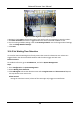
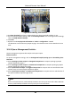
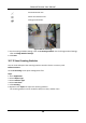
Table Of Contents
- Chapter 1 System Requirement
- Chapter 2 Device Activation and Accessing
- Chapter 3 Live View
- 3.1 Live View Parameters
- 3.1.1 Enable and Disable Live View
- 3.1.2 Adjust Aspect Ratio
- 3.1.3 Live View Stream Type
- 3.1.4 Select the Third-Party Plug-in
- 3.1.5 Light
- 3.1.6 Count Pixel
- 3.1.7 Start Digital Zoom
- 3.1.8 Auxiliary Focus
- 3.1.9 Lens Initialization
- 3.1.10 Quick Set Live View
- 3.1.11 Lens Parameters Adjustment
- 3.1.12 Conduct 3D Positioning
- 3.2 Set Transmission Parameters
- 3.3 Set Smooth Streaming
- 3.1 Live View Parameters
- Chapter 4 Video and Audio
- Chapter 5 Video Recording and Picture Capture
- Chapter 6 Event and Alarm
- 6.1 Basic Event
- 6.2 Smart Event
- 6.2.1 Detect Audio Exception
- 6.2.2 Set Defocus Detection
- 6.2.3 Detect Scene Change
- 6.2.4 Set Face Detection
- 6.2.5 Set Video Loss
- 6.2.6 Set Intrusion Detection
- 6.2.7 Set Line Crossing Detection
- 6.2.8 Set Region Entrance Detection
- 6.2.9 Set Region Exiting Detection
- 6.2.10 Set Unattended Baggage Detection
- 6.2.11 Set Object Removal Detection
- 6.2.12 Draw Area
- 6.2.13 Set Size Filter
- Chapter 7 Network Settings
- Chapter 8 Arming Schedule and Alarm Linkage
- Chapter 9 System and Security
- 9.1 View Device Information
- 9.2 Search and Manage Log
- 9.3 Simultaneous Login
- 9.4 Import and Export Configuration File
- 9.5 Export Diagnose Information
- 9.6 Reboot
- 9.7 Restore and Default
- 9.8 Upgrade
- 9.9 View Open Source Software License
- 9.10 Wiegand
- 9.11 Metadata
- 9.12 Time and Date
- 9.13 Set RS-485
- 9.14 Set RS-232
- 9.15 Power Consumption Mode
- 9.16 External Device
- 9.17 Security
- 9.18 Certificate Management
- 9.19 User and Account
- Chapter 10 Allocate VCA Resource
- Chapter 11 Open Platform
- Chapter 12 Smart Display
- Chapter 13 Set EPTZ
- Chapter 14 Pattern Linkage
- A. Device Command
- B. Device Communication Matrix

Network Camera User Manual
97
10.4.4 Set Shield Region
The shield region allows you to set the specific region in which the set smart function rule is
invalid.
Steps
1. Select Shield Region.
2. Click to draw shield area. Repeat this step above to set more shield regions.
3. Optional: Click to delete the drawn areas.
4. Click Save.
10.5 Face Counting
Face counting detection can remove the duplicate faces and calculate the number of objects
entered or exited a certain configured area.
Note
● For certain device models, you need to select Face Counting on VCA Resource page first.
● Only certain camera models support this function.
10.5.1 Set Face Counting Detection Rule
After setting the face counting detection rules and algorithm parameters, the device captures
targets and triggers linkage actions automatically.
Steps
1. Go to Configuration → Face Counting → Rule.
2. Check Rule.
3. Enter the min. pupil distance in the text field, or click to draw the min. pupil distance. The
distance of the drawn pupil will be displayed on the box below the live view.
Min. Pupil Distance
The min. pupil distance refers to the minimum square size composed by the area between
two pupils, and it is the basic standard for a camera to identify a target.
4. Enter the max. pupil distance in the text field, or click to draw the max. pupil distance.
Max. Pupil Distance
The max. pupil distance refers to the maximum square size composed by the area between
two pupils, and it is the basic standard for a camera to identify a target.
5. Click to draw the detection area. Draw an area by left-clicking end-points in the live view
window, and right-clicking to finish the area drawing.
6. Click to draw the detection line. The arrow shows entering direction, you can click to
change the direction.
● If the target crosses the counting area along the entering direction and crosses the detection