
User's Manual
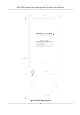

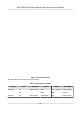
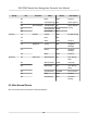
Table Of Contents
- Legal Information
- Symbol Conventions
- Regulatory Information
- Safety Instruction
- Available Models
- Chapter 1 Overview
- Chapter 2 Appearance
- Chapter 3 Installation
- Chapter 4 Wiring
- Chapter 5 Activation
- Chapter 6 Quick Operation
- Chapter 7 Basic Operation
- Chapter 8 Operation via Web Browser
- 8.1 Login
- 8.2 Forget Password
- 8.3 Live View
- 8.4 Person Management
- 8.5 Search Event
- 8.6 Configuration
- 8.6.1 Set Local Parameters
- 8.6.2 View Device Information
- 8.6.3 Set Time
- 8.6.4 Set DST
- 8.6.5 View Open Source Software License
- 8.6.6 Upgrade and Maintenance
- 8.6.7 Log Query
- 8.6.8 Security Mode Settings
- 8.6.9 Certificate Management
- 8.6.10 Change Administrator's Password
- 8.6.11 Account Security Settings
- 8.6.12 View Device Arming/Disarming Information
- 8.6.13 Network Settings
- 8.6.14 Set Video and Audio Parameters
- 8.6.15 Customize Audio Content
- 8.6.16 Set Image Parameters
- 8.6.17 Set Supplement Light Brightness
- 8.6.18 Time and Attendance Settings
- 8.6.19 General Settings
- 8.6.20 Video Intercom Settings
- 8.6.21 Access Control Settings
- 8.6.22 Set Biometric Parameters
- 8.6.23 Set Theme
- Chapter 9 Client Software Configuration
- 9.1 Configuration Flow of Client Software
- 9.2 Device Management
- 9.3 Group Management
- 9.4 Person Management
- 9.4.1 Add Organization
- 9.4.2 Configure Basic Information
- 9.4.3 Issue a Card by Local Mode
- 9.4.4 Upload a Face Photo from Local PC
- 9.4.5 Take a Photo via Client
- 9.4.6 Collect Face via Access Control Device
- 9.4.7 Collect Fingerprint via Client
- 9.4.8 Collect Fingerprint via Access Control Device
- 9.4.9 Configure Access Control Information
- 9.4.10 Customize Person Information
- 9.4.11 Configure Resident Information
- 9.4.12 Configure Additional Information
- 9.4.13 Import and Export Person Identify Information
- 9.4.14 Import Person Information
- 9.4.15 Import Person Pictures
- 9.4.16 Export Person Information
- 9.4.17 Export Person Pictures
- 9.4.18 Get Person Information from Access Control Device
- 9.4.19 Move Persons to Another Organization
- 9.4.20 Issue Cards to Persons in Batch
- 9.4.21 Report Card Loss
- 9.4.22 Set Card Issuing Parameters
- 9.5 Configure Schedule and Template
- 9.6 Set Access Group to Assign Access Authorization to Persons
- 9.7 Configure Advanced Functions
- 9.7.1 Configure Device Parameters
- 9.7.2 Configure Remaining Open/Closed
- 9.7.3 Configure Multi-Factor Authentication
- 9.7.4 Configure Card Reader Authentication Mode and Schedule
- 9.7.5 Configure First Person In
- 9.7.6 Configure Anti-Passback
- 9.7.7 Configure Multi-door Interlocking
- 9.7.8 Configure Device Parameters
- 9.8 Configure Linkage Actions for Access Control
- 9.9 Door Control
- 9.10 Event Center
- 9.11 Time and Attendance
- Appendix A. Tips for Scanning Fingerprint
- Appendix B. Tips When Collecting/Comparing Face Picture
- Appendix C. Tips for Installation Environment
- Appendix D. Dimension
- Appendix F. Communication Matrix and Device Command

Figure 4-1 Terminal Diagram
The
descripons of the terminals are as follows:
Table 4-1 Terminal Descripons
Group No. Funcon Color Name Descripon
Group A A1 Power Input Red +12 ~ 24 VDC Power Supply
A2 Black GND Ground
Group B B1 Alarm Input Yellow/Blue IN1 Alarm Input 1
DS-K1T681 Series Face Recognion Terminal User Manual
11