
User's Manual
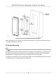

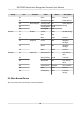
Table Of Contents
- Legal Information
- Symbol Conventions
- Regulatory Information
- Safety Instruction
- Available Models
- Chapter 1 Overview
- Chapter 2 Appearance
- Chapter 3 Installation
- Chapter 4 Wiring
- Chapter 5 Activation
- Chapter 6 Quick Operation
- Chapter 7 Basic Operation
- Chapter 8 Operation via Web Browser
- 8.1 Login
- 8.2 Forget Password
- 8.3 Live View
- 8.4 Person Management
- 8.5 Search Event
- 8.6 Configuration
- 8.6.1 Set Local Parameters
- 8.6.2 View Device Information
- 8.6.3 Set Time
- 8.6.4 Set DST
- 8.6.5 View Open Source Software License
- 8.6.6 Upgrade and Maintenance
- 8.6.7 Log Query
- 8.6.8 Security Mode Settings
- 8.6.9 Certificate Management
- 8.6.10 Change Administrator's Password
- 8.6.11 Account Security Settings
- 8.6.12 View Device Arming/Disarming Information
- 8.6.13 Network Settings
- 8.6.14 Set Video and Audio Parameters
- 8.6.15 Customize Audio Content
- 8.6.16 Set Image Parameters
- 8.6.17 Set Supplement Light Brightness
- 8.6.18 Time and Attendance Settings
- 8.6.19 General Settings
- 8.6.20 Video Intercom Settings
- 8.6.21 Access Control Settings
- 8.6.22 Set Biometric Parameters
- 8.6.23 Set Theme
- Chapter 9 Client Software Configuration
- 9.1 Configuration Flow of Client Software
- 9.2 Device Management
- 9.3 Group Management
- 9.4 Person Management
- 9.4.1 Add Organization
- 9.4.2 Configure Basic Information
- 9.4.3 Issue a Card by Local Mode
- 9.4.4 Upload a Face Photo from Local PC
- 9.4.5 Take a Photo via Client
- 9.4.6 Collect Face via Access Control Device
- 9.4.7 Collect Fingerprint via Client
- 9.4.8 Collect Fingerprint via Access Control Device
- 9.4.9 Configure Access Control Information
- 9.4.10 Customize Person Information
- 9.4.11 Configure Resident Information
- 9.4.12 Configure Additional Information
- 9.4.13 Import and Export Person Identify Information
- 9.4.14 Import Person Information
- 9.4.15 Import Person Pictures
- 9.4.16 Export Person Information
- 9.4.17 Export Person Pictures
- 9.4.18 Get Person Information from Access Control Device
- 9.4.19 Move Persons to Another Organization
- 9.4.20 Issue Cards to Persons in Batch
- 9.4.21 Report Card Loss
- 9.4.22 Set Card Issuing Parameters
- 9.5 Configure Schedule and Template
- 9.6 Set Access Group to Assign Access Authorization to Persons
- 9.7 Configure Advanced Functions
- 9.7.1 Configure Device Parameters
- 9.7.2 Configure Remaining Open/Closed
- 9.7.3 Configure Multi-Factor Authentication
- 9.7.4 Configure Card Reader Authentication Mode and Schedule
- 9.7.5 Configure First Person In
- 9.7.6 Configure Anti-Passback
- 9.7.7 Configure Multi-door Interlocking
- 9.7.8 Configure Device Parameters
- 9.8 Configure Linkage Actions for Access Control
- 9.9 Door Control
- 9.10 Event Center
- 9.11 Time and Attendance
- Appendix A. Tips for Scanning Fingerprint
- Appendix B. Tips When Collecting/Comparing Face Picture
- Appendix C. Tips for Installation Environment
- Appendix D. Dimension
- Appendix F. Communication Matrix and Device Command

Chapter 4 Wiring
The device supports connecng to the RS-485 terminal, the door lock, the exit buon, the alarm
output/input devices, the Wiegand card reader, the access controller, and the power supply. You
can wire the peripherals according to the descripons below.
If connect the Wiegand card reader with the access controller, the face recognion terminal can
transmit the authencaon informaon to the access controller and the access controller can
judge whether to open the door or not.
Note
●
If the c
able size is 18 AWG, you should use a 12 V switched-mode power supply. And the
distance between the power supply and the device should be no more than 20 m.
●
If the cable size is 15 AWG, you should use a 12 V switched-mode power supply. And the
distance between the power supply and the device should be no more than 30 m.
●
If the cable size is 12 AWG, you should use a 12 V switched-mode power supply. And the
distance between the power supply and the device should be no more than 40 m.
4.1 Terminal
Descripon
The terminals contains power input, alarm input, alarm output, RS-485, Wiegand output, and door
lock.
The terminal's diagram is as follows:
DS-K1T681 Series Face
Recognion Terminal User Manual
10