Network Traffic Camera • User Manual High Performance Event Detection Server Installation Guide
High Performance Event Detection Server • Installation Guide © 2019 Hangzhou Hikvision Digital Technology Co., Ltd. All rights reserved. This Manual is the property of Hangzhou Hikvision Digital Technology Co., Ltd. or its affiliates (hereinafter referred to as “Hikvision”), and it cannot be reproduced, changed, translated, or distributed, partially or wholly, by any means, without the prior written permission of Hikvision.
High Performance Event Detection Server • Installation Guide Regulatory Information FCC Information Please take attention that changes or modification not expressly approved by the party responsible for compliance could void the user’s authority to operate the equipment. FCC compliance: This equipment has been tested and found to comply with the limits for a Class A digital device, pursuant to part 15 of the FCC Rules.
High Performance Event Detection Server • Installation Guide Symbol Conventions The symbols that may be found in this document are defined as follows. Symbol Description Provides additional information to emphasize or supplement important points of the main text. Indicates a potentially hazardous situation, which if not avoided, could result in equipment damage, data loss, performance degradation, or unexpected results.
High Performance Event Detection Server • Installation Guide To avoid heat accumulation, good ventilation is required for a proper operating environment. Store the device in dry, well-ventilated, corrosive-gas-free, no direct sunlight, and no heating source environment. Avoid fire, water, and explosive environment when using the device. Avoid lightning strike for device installation. Install a lightning arrester if Transportation , Use, and Storage necessary.
High Performance Event Detection Server • Installation Guide TABLE OF CONTENTS Chapter 1 Appearance and Interfaces ............................................................................................ 6 Front Panel .......................................................................................................................... 6 Rear Panel ........................................................................................................................... 6 Chapter 2 Installation ....
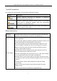
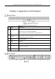
High Performance Event Detection Server • Installation Guide Chapter 1 Appearance and Interfaces Front Panel Front Panel Interfaces Front Panel Interfaces Description No. Name Description 1 Power Indicator Press it to power on. Press it for 3 s to forcibly shutdown. The indicator turns blue when servers power on. System Status Indicator Solid blue in normal status. 3 Reset Press it to reset. 4 USB USB 2.0. 5 Alarm Indicator Solid red indicates that the main board is abnormal.
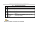
High Performance Event Detection Server • Installation Guide Rear Panel Interfaces Description No. Name Description 1 LAN 1/LAN 2 Gigabit data Ethernet. 2 LAN A/LAN B Management Ethernet. 3 Debugging Interface Debug device. 4 USB USB 3.0. 5 Redundancy 1+1 Power Input Interface Connect power supply. Redundancy power supply design achieves high availability. Panel may vary in different models, please refer to actual server.
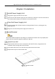
High Performance Event Detection Server • Installation Guide Chapter 2 Installation Install Power Supply Unit Align power supply unit with the unit track. Insert the rear side of power supply unit into node slots, and push it into the track until the front side of power supply unit is parallel to rear panel of server. Take Out Power Supply Unit Push blue breech lock of power supply unit along left side of server, and drag out it by gripping handle.
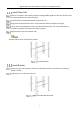
High Performance Event Detection Server • Installation Guide Install Outer Rail Select a 1 U space in the bracket. Install the equipped M5 caged nuts with 6 in the front and 4 in the back to the inner side of bracket. Assemble the front half and back half of the outer rail. Drag out the back half of the outer rail (marked with back) and adjust the length. Fix the front half (marked with front) and back half of the outer rail in the front and rear bracket by 2 groups of 10 M5 screws and cup washer.
High Performance Event Detection Server • Installation Guide Push the server into the bracket along outer rail, until the server is pushed into the inner of the bracket. Fix the server to chassis by 2 groups of 16 M5 screws and cup washer. Fix the Server When drag out the server from bracket, pull the plastic pick upward in left side, and pull the plastic pick downward in right side.
UD16955B