Network Video Recorder User Manual
Network Video Recorder User Manual Legal Information About this Manual The Manual includes instructions for using and managing the Product. Pictures, charts, images and all other information hereinafter are for description and explanation only. The information contained in the Manual is subject to change, without notice, due to firmware updates or other reasons.
Network Video Recorder User Manual TO ANY NUCLEAR EXPLOSIVE OR UNSAFE NUCLEAR FUEL-CYCLE, OR IN SUPPORT OF HUMAN RIGHTS ABUSES. IN THE EVENT OF ANY CONFLICTS BETWEEN THIS MANUAL AND THE APPLICABLE LAW, THE LATER PREVAILS.
Network Video Recorder User Manual Regulatory Information FCC Information Please take attention that changes or modification not expressly approved by the party responsible for compliance could void the user's authority to operate the equipment. FCC compliance: This equipment has been tested and found to comply with the limits for a Class A digital device, pursuant to part 15 of the FCC Rules.
Network Video Recorder User Manual Industry Canada ICES-003 Compliance This device meets the CAN ICES-3 (A)/NMB-3(A) standards requirements.
Network Video Recorder User Manual Applicable Model This manual is applicable to the following models.
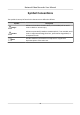
Network Video Recorder User Manual Symbol Conventions The symbols that may be found in this document are defined as follows. Symbol Description Danger Indicates a hazardous situation which, if not avoided, will or could result in death or serious injury. Caution Indicates a potentially hazardous situation which, if not avoided, could result in equipment damage, data loss, performance degradation, or unexpected results.
Network Video Recorder User Manual Safety Instruction • Proper configuration of all passwords and other security settings is the responsibility of the installer and/or user. • In the use of the product, you must be in strict compliance with the electrical safety regulations of the nation and region. Please refer to technical specifications for detailed information.
Network Video Recorder User Manual Preventive and Cautionary Tips Before connecting and operating your device, please be advised of the following tips: • • • • • • • • • • Ensure recorder is installed in a well-ventilated, dust-free environment. Recorder is designed for indoor use only. Keep all liquids away from the device. Ensure environmental conditions meet factory specifications. Ensure recorder is properly secured to a rack or shelf.
Network Video Recorder User Manual Contents Chapter 1 Basic Operation .......................................................................................................... 1 1.1 Activate Your Device .............................................................................................................. 1 1.1.1 Default User and IP Address ......................................................................................... 1 1.1.2 Activate via Local Menu ......................................
Network Video Recorder User Manual 3.2 Configure Auto-Switch of Cameras ...................................................................................... 19 3.3 Digital Zoom ......................................................................................................................... 20 3.4 Fisheye View ........................................................................................................................ 20 3.5 POS Information Overlay .......................................
Network Video Recorder User Manual 4.1.8 Configure Event Triggered Recording .......................................................................... 36 4.1.9 Configure Alarm Triggered Recording ......................................................................... 36 4.1.10 Configure Picture Capture ......................................................................................... 37 4.1.11 Configure Holiday Recording .............................................................................
Network Video Recorder User Manual 5.1.3 Configure Video Tampering Alarms ............................................................................ 49 5.1.4 Configure Sensor Alarms ............................................................................................. 50 5.1.5 Configure Exceptions Alarms ...................................................................................... 50 5.2 VCA Event Alarm .......................................................................................
Network Video Recorder User Manual 6.2 Work Behavior Analysis ........................................................................................................ 69 6.2.1 Absence/Sleep On Duty Detection .............................................................................. 69 6.2.2 People Overstay Detection .......................................................................................... 70 6.2.3 Number of People Exception Detection .....................................................
Network Video Recorder User Manual Chapter 7 File Management .................................................................................................... 100 7.1 Search Files ........................................................................................................................ 100 7.2 Export Files ........................................................................................................................ 100 7.3 Smart Search .............................................
Network Video Recorder User Manual Chapter 12 User Management and Security ............................................................................ 129 12.1 Manage User Accounts .................................................................................................... 129 12.1.1 Add a User ............................................................................................................... 129 12.1.2 Edit the Admin User ................................................................
Network Video Recorder User Manual 13.4.3 HDD Health Detection ............................................................................................. 144 13.4.4 Configure Disk Clone ............................................................................................... 144 13.4.5 Repair Database ...................................................................................................... 145 13.5 Upgrade Device .........................................................................
Network Video Recorder User Manual 14.2.10 Why is image getting stuck when the video recorder is playing back by single or multi-channel cameras? ..................................................................................................... 155 14.2.11 Why does my video recorder make a beeping sound after booting? ................... 155 14.2.12 Why is there no recorded video after setting the motion detection? .................. 155 14.2.13 Why is the sound quality not good in recording video? .....
Network Video Recorder User Manual Chapter 1 Basic Operation 1.1 Activate Your Device 1.1.1 Default User and IP Address • Default administrator account: admin. • Default IPv4 address: 192.168.1.64. 1.1.2 Activate via Local Menu For the first-time access, you need to activate the device by setting an admin password. No operation is allowed before activation. You can also activate the device via Web Browser, SADP or Client Software. Steps 1. Enter the admin password twice.
Network Video Recorder User Manual Figure 1-1 Activate via Local Menu Warning We highly recommend you to create a strong password of your own choosing (using a minimum of 8 characters, including at least three kinds of following categories: upper case letters, lower case letters, numbers, and special characters) in order to increase the security of your product.
Network Video Recorder User Manual What to do next • When you have enabled Export GUID, continue to export the GUID file to the USB flash driver for the future password resetting. • When you have enabled Security Question Configuration, continue to set the security questions for the future password resetting. 1.1.3 Activate via SADP SADP software is used for detecting the online device, activating the device, and resetting its password.
Network Video Recorder User Manual 1.1.4 Activate via Client Software The client software is versatile video management software for multiple kinds of devices. Before You Start Get the client software from the supplied disk or the official website, and install the software according to the prompts. Steps 1. Run the client software and the control panel of the software pops up, as shown below. Figure 1-3 Control Panel 2. Click Device Management to enter the Device Management interface, as shown below.
Network Video Recorder User Manual Figure 1-4 Device Management Interface 3. Check the recorder status from the device list, and select an inactive recorder. 4. Click Activate to pop up the Activation interface. 5. Create a password and input the password in the password field, and confirm the password.
Network Video Recorder User Manual 7. Click Modify Netinfo to pop up the Network Parameter Modification interface, as shown below. Figure 1-6 Modify Network Parameters 8. Change the recorder IP address to the same subnet with your computer. - Modify the IP address manually. - Check Enable DHCP. 9. Input the password to activate your IP address modification. 1.1.5 Activate via Web Browser You can get access to the recorder via web browser.
Network Video Recorder User Manual Note We highly recommend you to create a strong password of your own choosing (using a minimum of 8 characters, including at least three kinds of following categories: upper case letters, lower case letters, numbers, and special characters) in order to increase the security of your product. And we recommend you change your password regularly, especially in the high security system, changing the password monthly or weekly can better protect your product. 3. Click OK. 1.
Network Video Recorder User Manual Note • Check Enable DHCP to obtain IP settings automatically if a DHCP server is available on the network. • Valid MTU value range is 500 to 9676. 1.3 HDD Settings Ensure the video recorder storage media is well. You can install at least one HDD and initialize it, or create a RAID and initialize it. 1.4 Add Network Camera Before you can get live video or record the video files, you must add the network cameras to the connection list of the device.
Network Video Recorder User Manual 1.4.1 Add Automatically Searched Online Network Camera Steps 1. Click on the main menu. 2. Click Number of Unadded Online Device at the bottom. 3. Select the automatically searched online network cameras. 4. Click Add to add the camera which has the same login password with the video recorder.
Network Video Recorder User Manual Figure 1-11 Add Network Camera 4. Optional: Check Use Channel Default Password to use the default password to add the camera. 5. Optional: Check Use Default Port to use the default management port to add the camera. For SDK service, the default port value is 8000. For enhanced SDK service, the default value is 8443. Note The function is only available when you use HIKVISION protocol. 6. Optional: Check Verify Certificate to verify the camera with certificate.
Network Video Recorder User Manual Figure 1-12 Protocol Management 2. Set protocol parameters. Type The network camera adopting custom protocol must support getting stream through standard RTSP. Path Contact the manufacturer of network camera for the URL (Uniform Resource Locator) of getting main stream and sub-stream. Note The protocol type and the transfer protocol must be supported by the network camera to add. 3. Click OK. After adding the customized protocol, you can see it in Protocol. 1.
Network Video Recorder User Manual 2) Scan the QR code to read the service terms and privacy statement. 3) Check The Guarding Vision service will require internet access. Please read Service Terms and Privacy Statement before enabling the service if you agree the service terms and privacy statement. 4) Click OK. Note • Guarding Vision is disabled by default. • The verification code is empty by default. It must contain 6 to 12 letters or numbers, and it is case sensitive. 3.
Network Video Recorder User Manual Chapter 2 Camera Settings 2.1 Configure Image Parameters You can customize image parameters, including day/night switch, backlight, contrast, and saturation in Camera → Display . Image Settings Customize the image parameters including brightness, contrast, and saturation. Exposure Set the camera exposure time (1/10000 to 1 sec). A larger exposure value results in a brighter image.
Network Video Recorder User Manual Figure 2-1 OSD Configuration Interface 6. Drag the text frame on the preview window to adjust the OSD position. 7. Click Apply. 2.3 Configure Privacy Mask The privacy mask protects personal privacy by concealing parts of the image from kive view or recording with a masked area. Steps 1. Go to Camera → Privacy Mask . 2. Select a camera to set privacy mask. 3. Check Enable. 4. Draw a zone on the window. The zone will be marked by different frame colors.
Network Video Recorder User Manual Figure 2-2 Privacy Mask Settings Interface Note • Up to 4 privacy masks zones can be configured and the size of each area can be adjusted. • You can clear the configured privacy mask zones on the window by clicking the corresponding clear zone 1 to 4 icons on the right of the window, or click Clear All to clear all zones. 5. Click Apply. 2.4 IP Camera Time Sync The device can automatically synchronize the time of connected IP camera after enabling this function. Steps 1.
Network Video Recorder User Manual 2.5 Import/Export IP Camera Configuration Files The IP camera information, including the IP address, manage port, password of admin, etc., can be saved in Microsoft Excel format and backed up to the local device. The exported file can be edited on a PC, including adding or deleting the content, and copying the setting to other devices by importing the Excel file to it.
Network Video Recorder User Manual Chapter 3 Live View Live view displays the video image getting from each camera in real time. 3.1 Start Live View Click on the main menu bar to enter the Live View. • Select a window and double click a camera from the list to play the video from the camera in the selected window. • Use the toolbar at the playing window bottom to realize the capture, instant playback, audio on/ off, digital zoom, live view strategy, show information and start/stop recording, etc. 3.1.
Network Video Recorder User Manual Volume Adjust the Live View volume, playback and two-way audio for the selected output interface. Event Output Select the output to show event video. Full Screen Monitoring Dwell Time Set the time in seconds to show alarm event screen. 3. Click OK. 3.1.2 Configure Live View Layout Live view displays the video image getting from each camera in real time. Configure Custom Live View Layout Steps 1. Go to System → Live View → View . 2. Click Set Custom Layout. 3.
Network Video Recorder User Manual The successfully configured layout is displayed in the list. 8. Optional: Select a live view layout from the list and click delete the name. to edit the name, or click to Configure Live View Mode Steps 1. Go to System → Live View → View . 2. Select the video output interface. 3. Select a layout or custom layout from the toolbar. 4. Select a division window, and double-click on a camera in the list to link the camera to the window.
Network Video Recorder User Manual 3.3 Digital Zoom Digital Zoom zooms into the live image in different magnifications (1x to 16x). Steps 1. Start live view, click from the toolbar. 2. Move the sliding bar or scroll the mouse wheel to zoom in/out the image to different magnifications (1x to 16x). Figure 3-3 Digital Zoom 3.4 Fisheye View The device supports the fisheye camera expansion in Live View or playback mode.
Network Video Recorder User Manual the 180° panorama view. PTZ Expansion ( ) the 360° panorama view. The PTZ Expansion is the close-up view of some defined area in the fisheye view or panorama expansion. It supports the electronic PTZ function, also called e-PTZ. Radial Expansion ( ) In radial expansion mode, the whole wideangle view of the fisheye camera is displayed. This view mode is called Fisheye View because it approximates the vision of a fish’s convex eye.
Network Video Recorder User Manual Steps 1. Start live view, and click . 2. Zoom in/out the image. - Zoom in: Click on the desired position in the video image and drag a rectangle area in the lower right direction to zoom in. - Zoom out: Drag a rectangle area in the upper left direction to move the position to the center and enable the rectangle area to zoom out. 3.7 Live View Strategy Steps 1. In the live view mode, click to enter the digital zoom operation interface in full screen mode. 2.
Network Video Recorder User Manual Main port All operations are available for main port. Aux port You can switch to aux port to do some basic operations, like playback, switching live view image. Third port You can only preview camera image in third port.
Network Video Recorder User Manual Figure 3-5 PTZ Parameters Settings 3. Edit the PTZ parameters. Note All the parameters should be exactly match the PTZ camera parameters. 4. Click OK to save the settings. 3.10.2 Set a Preset Presets record the PTZ position and the status of zoom, focus, iris, etc.You can call a preset to quickly move the camera to the predefined position. Steps 1. Click on the quick settings toolbar of the PTZ camera's live view. 2.
Network Video Recorder User Manual Figure 3-7 View the Configured Presets 3.10.3 Call a Preset A preset enables the camera to point to a specified position such as a window when an event takes place. Steps 1. Click on the quick settings toolbar of the PTZ camera's Live View. 2. Click in the lower right corner of Live View to set the preset. 3. Select the preset No. from the drop-down list. 4.
Network Video Recorder User Manual 3. Select the patrol No. 4. Click Set. 5. Click Figure 3-11 Patrol Settings to add a key point to the patrol. Figure 3-12 Key Point Configuration 1) Configure key point parameters. Preset Determines the order the PTZ will follow while cycling through the patrol. Speed Defines the speed the PTZ will move from one key point to the next. Duration Refers to the duration to stay at the corresponding key point. 2) Click Apply to save the key points to the patrol. 6.
Network Video Recorder User Manual Operation Description Operation Description Select a key point to delete. Edit the added key point. Adjust the key point order Adjust the key point order 7. Click Apply to save the patrol settings. 3.10.5 Call a Patrol Calling a patrol makes the PTZ move according to the predefined patrol path. Steps 1. Click on the quick settings toolbar of the PTZ camera's live view. 2. Click Patrol on the PTZ control panel. Figure 3-13 Patrol Configuration 3. Select a patrol.
Network Video Recorder User Manual Figure 3-14 Pattern Configuration 3. Select the pattern No. 4. Set the pattern. 1) Click Record to start recording. 2) Click corresponding buttons on the control panel to move the PTZ camera. 3) Click Stop to stop recording. The PTZ movement is recorded as the pattern. 3.10.7 Call a Pattern Follow the procedure to move the PTZ camera according to the predefined patterns. Steps 1. Click on the quick settings toolbar of the PTZ camera's live view. 2.
Network Video Recorder User Manual Note This function is supported only by some certain models. Steps 1. Click on the quick settings toolbar of the PTZ camera's live view. 2. Click directional buttons to wheel the camera to a location, and click Left Limit or Right Limit to link the location to the corresponding limit. Note The speed dome linear scans from the left limit to the right limit, and you must set the left limit on the left side of the right limit.
Network Video Recorder User Manual 3.10.10 Auxiliary Functions You can operate the auxiliary functions including light, wiper, 3D positioning, and center on the PTZ control panel. Before You Start Make sure the connected IP camera supports the PTZ function, and is properly connected. Steps 1. on the quick settings toolbar of the PTZ camera's live view. The PTZ control panel Click displays on the right of the interface. 2. Click Aux Function. Figure 3-16 Aux Function Configuration 3.
Network Video Recorder User Manual Chapter 4 Recording and Playback 4.1 Recording 4.1.1 Configure Recording Parameters Go to Camera → Video Parameters . Main Stream Main stream refers to the primary stream that affects data recorded to the hard disk drive and will directly determine your recording quality and image size. Comparing with the sub-stream, the main stream can provide a higher quality video with higher resolution and frame rate.
Network Video Recorder User Manual Sub-Stream Sub-stream is a second codec that runs alongside the main stream. It allows you to reduce the outgoing internet bandwidth without sacrificing your direct recording quality. Sub-stream is often exclusively used by apps to view live video. Users with limited internet speeds may benefit most from this setting. Picture The picture refers to the live picture capture in continuous or event recording type.
Network Video Recorder User Manual The time you set to record before the scheduled time or event. For example, when an alarm triggers the recording at 10:00, and if you set the pre-record time as 5 seconds, the camera records at 9:59:55. Post-record The time you set to record after the event or the scheduled time. For example, when an alarm triggered recording ends at 11:00, and if you set the post-record time as 5 seconds, it records till 11:00:05.
Network Video Recorder User Manual 4.1.5 Configure Plan Recording The camera would automatically start/stop recording according to the configured recording schedule. Before You Start • Ensure you have installed the HDDs to the device or added the network disks before storing the video files, pictures and log files.
Network Video Recorder User Manual Figure 4-2 Record Schedule Note • You can repeat the above steps to set schedule recording or capture for each day in the week. • Continuous recording is applied to each day by default. 6. Optional: Copy the recording schedule to other camera(s). 1) Click Copy to. 2) Select camera(s) to duplicate with the same schedule settings. 3) Click OK. 7. Click Apply. 4.1.
Network Video Recorder User Manual 4.1.7 Configure Motion Detection Triggered Recording You can configure the recording triggered by the motion detection event. Steps 1. Go to System → Event → Normal Event → Motion Detection . 2. Configure the motion detection and select the channel (s) to trigger the recording when motion event occurs. Refer to Configure Linkage Actions for details. 3. Go to Camera → Encoding Parameters → Recording Parameters . 4.
Network Video Recorder User Manual 7. Drag the mouse on the time bar to set the alarm recording schedule. Refer to Configure Plan Recording for details. 4.1.10 Configure Picture Capture The picture refers to the live picture capture in continuous or event recording type. Only certain models support this function. Steps 1. Go to Camera → Encoding Parameters → Capture . 2. Set the picture parameters. Resolution Set the resolution of the picture to capture.
Network Video Recorder User Manual Figure 4-3 Edit Holiday Settings 5. Set Holiday Name, Mode, Start Date, and End Date. 6. Click OK. 7. Set the schedule for holiday recording. Refer to Configure Plan Recording for details. 4.1.12 Configure Redundant Recording and Capture Enabling redundant recording and capture, which means saving the record files and captured pictures not only in the R/W HDD but also in the redundant HDD, will effectively enhance the data safety and reliability.
Network Video Recorder User Manual Figure 4-4 Record Parameters 6. Check Redundant Record/Capture. 7. Click OK to save settings. 4.2 Playback 4.2.1 Instant Playback Instant playback enables the device to play the recorded video files recorded in the last five minutes. If no video is found, it means there is no recording during the last five minutes. After selecting the camera on Live View, you can move the cursor to the window bottom to access the toolbar, and click to start instant playback.
Network Video Recorder User Manual Figure 4-5 Playback Interface 4.2.2 Play Normal Video Go to Playback, select date and camera(s), and use the toolbar at the bottom to perform playback operations. Refer to Playback Operations . You can click camera(s) to execute simultaneous playback of multiple camera(s). Note 256x playing speed is supported.
Network Video Recorder User Manual 4.2.3 Play Smart Searched Video In smart playback mode, the device can analyze videos that containing motion, line, or intrusion detection information, and mark them in red. Go to Playback, click Smart, and then click motion detection ( ), line crossing detection ( intrusion detection ( ) in the toolbar at the bottom to play the video as your desire. Figure 4-7 Payback by Smart Search 4.2.4 Play Custom Searched Files You can play video by customized search conditions.
Network Video Recorder User Manual 5. Click Search. Figure 4-9 Custom Searched Video Files 6. Select a file and start playing the video on search results interface. 4.2.5 Play Tag Files Video tag allows you to record information, such as people and locations of a certain time point, during playback. You can use video tag(s) to search video files and position time point. Add Tag Files Steps 1. Go to Playback. 2. Search and play back the video file(s). 3. Click to add the tag. 4. Edit the tag information.
Network Video Recorder User Manual Figure 4-10 Tag Search 4. Click Search. Figure 4-11 Searched Tag Files 5. Select a tag file, and play the video on the search results interface. 4.2.6 Play by Sub-periods The video files can be played in multiple sub-periods simultaneously on the screen. Steps 1. Go to Playback. 2. Click at the lower-left corner. 3. Select a camera. 4. Set the start time and end time for searching video. 5. Select the different multi-period at the lower-right corner, e.g., 4-Period.
Network Video Recorder User Manual 4.2.7 Play Log Files Play back record file(s) associated with channels after searching system logs. Steps 1. Go to Maintenance → Log Information . 2. Click Log Search . 3. Set search time and type and click Search. Figure 4-12 System Log Search Interface 4. Choose a log with a video file and click to start playing the log file. 4.2.8 Play External Files You can play files from external storage devices.
Network Video Recorder User Manual 4.3 Playback Operations 4.3.1 Normal/Important/Custom Video During the playback, you can select the following three modes to play the video. Normal Video files from the continuous recording. Important Video files from the event and alarm recording triggered recording. Custom Video files searched by custom conditions. 4.3.
Network Video Recorder User Manual 4.3.4 Switch between Main Stream and Sub-Stream You can switch between the main stream and the sub-stream during the playback. Icon Description Play the video in main stream. Play the video in sub-stream. Note The encoding parameters for the main stream and sub-stream can be configured in Storage → Encoding Parameters . 4.3.5 Thumbnails View With the thumbnails view on the playback interface, you can conveniently locate the required video files on the time bar.
Network Video Recorder User Manual 180° Panorama ( ) Switch the Live View image to the 180° panorama view. 360° Panorama ( ) Switch the Live View image to the 360° panorama view. PTZ Expansion ( ) The PTZ Expansion is the close-up view of some defined area in the fisheye view or panorama expansion. It supports the electronic PTZ function, also called e-PTZ. Radial Expansion ( ) In radial expansion mode, the whole wideangle view of the fisheye camera is displayed.
Network Video Recorder User Manual 4.3.8 Fast View Hold the mouse to drag on the time bar to get a fast view of the video files. In the Video Playback mode, hold and drag the mouse through the playing time bar to fast view the video files. Release the mouse at the required time point to enter the full-screen playback. 4.3.9 Digital Zoom Digital Zoom zooms into the live image in different magnifications (1x to 16x). Steps 1. Start live view, click from the toolbar. 2.
Network Video Recorder User Manual Chapter 5 Event 5.1 Normal Event Alarm 5.1.1 Configure Motion Detection Alarms Motion detection enables the device to detect the moving objects in the monitored area and trigger alarms. Steps 1. Go to System → Event → Normal Event → Motion Detection . 2. Select a camera. 3. Check Enable. 4. Set the motion detection area. Full screen Click to set the full-screen motion detection for the image.
Network Video Recorder User Manual 2. Select a camera. 3. Check Enable. 4. Set the video tampering area. Drag on the preview screen to draw the customized video tampering area. 5. Set Sensitivity (0-2). 3 levels are available. The sensitivity calibrates how readily movement triggers the alarm. A higher value more readily triggers the video tampering detection. 6. Set the arming schedule. Refer to Configure Arming Schedule . 7. Set linkage actions. Refer to Configure Linkage Actions . 5.1.
Network Video Recorder User Manual Figure 5-1 Event Hint Settings 3. Select an exception type. Figure 5-2 Exceptions Handling 4. Set the linkage actions. Refer to Configure Linkage Actions . 5.2 VCA Event Alarm The device supports receiving VCA detections sent by connected IP cameras. Enable and configure VCA detection on the IP camera settings interface first. Note • VCA detections must be supported by the connected IP camera.
Network Video Recorder User Manual Figure 5-3 Facial Detection 3. 4. 5. 6. Select a camera to configure. Check Enable Face Detection. Optional: Check Save VCA Picture to save the captured pictures of face detection. Set the detection sensitivity. Sensitivity range: [1-5]. The higher the value is, the more easily the face will be detected. 7. Set the arming schedule. Refer to Configure Arming Schedule . 8. Set linkage actions. Refer to Configure Linkage Actions . 9. Click Apply. 5.2.
Network Video Recorder User Manual Figure 5-4 Vehicle Detection 4. 5. 6. 7. 8. Check Enable Vehicle Detection. Optional: Check Save VCA Picture to save the captured vehicle detection pictures. Set the arming schedule. Refer to Configure Arming Schedule . Set the linkage actions. Refer to Configure Linkage Actions . Configure rules, including Area Settings, Picture, Overlay Content, and Blacklist and Whitelist. Area Settings Up to 4 lanes are selectable.
Network Video Recorder User Manual Figure 5-5 Loitering Detection 4. Check Enable Loitering Detection.. 5. Optional: Check Save VCA Picture to save the captured loitering detection pictures. 6. Set loitering detection parameters. 1) Select Arming Region. Up to 4 regions are selectable. 2) Set Time Threshold. Time Threshold The time of car staying in the region. If the value is 10, an alarm is triggered after the car has stayed in the region for 10s. Its range is [1s-10s]. 3) Set Sensitivity.
Network Video Recorder User Manual Figure 5-6 People Gathering Detection 4. Check Enable People Gathering Detection. 5. Optional: Check Save VCA Picture to save the captured people gathering detection pictures. 6. Set people gathering detection parameters. 1) Select Arming Region. Up to 4 regions are selectable. 2) Click Draw Area to draw a quadrilateral in the preview window by specifying four vertices of the area. 3) Set Percentage.
Network Video Recorder User Manual Figure 5-7 Fast moving detection 4. Check Enable Fast Moving. 5. Optional: Check Save VCA Picture to save the captured fast moving detection pictures. 6. Set fast moving detection parameters. 1) Select Arming Region. Up to 4 regions are selectable. 2) Click Draw Area to draw a quadrilateral in the preview window by specifying four vertices of the area. 3) Set Sensitivity. Sensitivity Similarity of the background image to the object.
Network Video Recorder User Manual Figure 5-8 Parking Detection 4. Check Enable Parking Detection. 5. Optional: Check Save VCA Picture to save the captured parking detection pictures. 6. Set parking detection parameters. 1) Select Arming Region. Up to 4 regions are selectable. 2) Set Time Threshold. Time Threshold The time of car staying in the region. If the value is 10, an alarm is triggered after the car has stayed in the region for 10s. Its range is [5s-20s]. 3) Set Sensitivity.
Network Video Recorder User Manual Figure 5-9 Unattended Baggage Detection 4. Check Enable Unattended Baggage Detection. 5. Optional: Check Save VCA Picture to save the captured unattended baggage detection pictures. 6. Set the detection rules and detection areas. 1) Select Arming Region. Up to 4 regions are selectable. 2) Drag the sliders to set Time Threshold and Sensitivity. Time Threshold The time of the objects are left in the region.
Network Video Recorder User Manual Figure 5-10 Object Removal Detection 4. Check Enable Object Removable Detection. 5. Optional: Check Save VCA Picture to save the captured object removable detection pictures. 6. Follow these steps to set the detection rules and detection areas. 1) Select Arming Region. Up to 4 regions are selectable. 2) Drag the sliders to set Time Threshold and Sensitivity. Time Threshold The time of the objects removed from the region.
Network Video Recorder User Manual Figure 5-11 Audio Exception Detection 4. Optional: Check Save VCA Picture to save the captured audio exception detection pictures. 5. Set the detection rules: 1) Select Exception Detection. 2) Check Audio Loss Exception,Sudden Increase of Sound Intensity Detection,and/or Sudden Decrease of Sound Intensity Detection. Audio Loss Exception Detects a steep sound rise in the surveillance scene.
Network Video Recorder User Manual Steps 1. Go to Smart Analysis → Smart Event Settings → Other Events . 2. Select a camera. 3. Click Defocus. Figure 5-12 Defocus Detection 4. Check Enable. 5. Optional: Check Save VCA Picture to save the captured defocus detection pictures. 6. Drag the Sensitivity slider to set the detection sensitivity. Sensitivity Ranges from 1 to 100, the higher the value, the more easily the defocus image will be detected. Note 7. Set the arming schedule.
Network Video Recorder User Manual Figure 5-13 Sudden Scene Change 4. Check Enable. 5. Optional: Check Save VCA Picture to save the captured sudden scene change detection pictures. 6. Drag the Sensitivity slider to set the detection sensitivity. Sensitivity Ranges from 1 to 100, the higher the value, the more easily the change of scene can trigger the alarm. Note 7. Set the arming schedule. Refer to Configure Arming Schedule . 8. Set the linkage actions. Refer to Configure Linkage Actions . 9. Click Apply.
Network Video Recorder User Manual Figure 5-14 PIR Alarm 4. 5. 6. 7. 8. Check PIR Alarm. Optional: Check Save VCA Picture to save the captured of PIR alarm pictures. Set the arming schedule. Refer to Configure Arming Schedule . Set the linkage actions. Refer to Configure Linkage Actions . Click Apply. 5.2.13 Thermal Camera Detection The NVR supports the event detection modes of the thermal network cameras: fire and smoke detection, temperature detection, temperature difference detection, etc.
Network Video Recorder User Manual 5.2.14 Configure Queue Management After connecting with queue management camera, you can set the arming schedule and linkage action of queue management. Before You Start Ensure the recorder have connected with queue management camera. Steps 1. Go to Smart Analysis → Smart Event Settings → Other Events . 2. Select a queue management camera. 3. Optional: Check Save VCA Picture to save the captured pictures of detection. 4. Set the arming schedule.
Network Video Recorder User Manual Figure 5-15 Set Arming Schedule 4. You can click Copy to copy the current day arming schedule settings to other day(s). 5. Click Apply to save the settings. 5.4 Configure Linkage Actions Alarm linkage actions will be activated when an alarm or exception occurs, including Event Hint Display, Full Screen Monitoring, Audible Warning (buzzer), Notify Surveillance Center, Trigger Alarm Output, and Send Email. 5.4.
Network Video Recorder User Manual Event Output Select the output to show the event video. Full Screen Monitoring Dwell Time Set the time in seconds to show the alarm event screen. If alarms are triggered simultaneously in several channels, their full-screen images will be switched at an interval of 10 seconds (default dwell time). 3. Go to the Linkage Action interface of the alarm detection (e.g., motion detection, video tampering, face detection, etc.). 4.
Network Video Recorder User Manual 4. Go to the Linkage Action interface of the alarm detection (e.g., motion detection, video tampering, face detection, etc.). 5. Select Send Email alarm linkage action. 5.4.5 Trigger Alarm Output The alarm output can be triggered by the alarm input, motion detection, video tampering detection, face detection, line crossing detection, and any all other events. Steps 1. Go to Linkage Action interface of the alarm detection (e.g.
Network Video Recorder User Manual Chapter 6 Smart Analysis 6.1 Engine Configuration Each engine processes a specified VCA type as its working mode. You can configure the engine working mode as your desire. Steps 1. Go to Smart Analysis → Smart Analysis → Engine Configuration . Figure 6-1 Engine Configuration 2. Configure each engine usage. You can view the engine temperature and linked channel status of each function.
Network Video Recorder User Manual 6.2 Work Behavior Analysis Work behavior analysis includes absence/sleep on duty detection, people overstay detection, number of people exception detection, and using mobile phone detection. You can configure behavior analysis via web browser. 6.2.1 Absence/Sleep On Duty Detection Absence detection detects people who leave duty area over the set time in detection area.
Network Video Recorder User Manual Figure 6-2 Absence/Sleep On Duty Detection 6. Set the arming schedule. Refer to Configure Arming Schedule . 7. Set linkage actions. Refer to Configure Linkage Actions . 8. Click Save. What to do next You can check to view the live detection result via GUI. Refer to Target Detection for details. 6.2.2 People Overstay Detection People overstay detection can trigger alarm when overstay time of the target is beyond the set value in the detection area.
Network Video Recorder User Manual Steps 1. Go to Configuration → VCA → Behavior Analysis . 2. Select a camera. 3. Check Enable Local VCA Behavior Analysis, and the device will analyze the video, cameras only transmit video stream. 4. Set Behavior Analysis Subtype as Work Behavior Analysis. 5. Set rules and detection areas. 1) Click to add a rule. 2) Select Rule Type as People Overstay Detection. 3) Enter the rule name. 4) Enable the rule. 5) Set Mode.
Network Video Recorder User Manual Figure 6-3 People Overstay Detection 6. Set the arming schedule. Refer to Configure Arming Schedule . 7. Set linkage actions. Refer to Configure Linkage Actions . 8. Click Save. What to do next You can check to view the live detection result via GUI. Refer to Target Detection for details. 6.2.
Network Video Recorder User Manual Steps 1. Go to Configuration → VCA → Behavior Analysis . 2. Select a camera. 3. Check Enable Local VCA Behavior Analysis, and the device will analyze the video, cameras only transmit video stream. 4. Set Behavior Analysis Subtype as Work Behavior Analysis. 5. Set rules and detection areas. 1) Click to add a rule. 2) Select Rule Type as Number of People Exception Detection. 3) Enter the rule name. 4) Enable the rule. 5) Set the duration time.
Network Video Recorder User Manual Figure 6-4 Number of People Exception Detection 6. Set the arming schedule. Refer to Configure Arming Schedule . 7. Set linkage actions. Refer to Configure Linkage Actions . 8. Click Save. What to do next You can check to view the live detection result via GUI. Refer to Target Detection for details. 6.2.4 Using Mobile Phone Detection Using mobile phone detection detects whether the person in the detection is using mobile phone.
Network Video Recorder User Manual 2. Select a camera. 3. Check Enable Local VCA Behavior Analysis, and the device will analyze the video, cameras only transmit video stream. 4. Set Behavior Analysis Subtype as Work Behavior Analysis. 5. Set rules and detection areas. 1) Click to add a rule. 2) Enter the rule name. 3) Enable the rule. 4) Set the duration time. It will trigger the alarm when the time exceeds the limit.
Network Video Recorder User Manual What to do next You can check to view the live detection result via GUI. Refer to Target Detection for details. 6.3 Street Behavior Analysis Street behavior analysis includes people gathering detection, people running detection, violent motion detection, and people falling down detection. You can configure behavior analysis via web browser. 6.3.
Network Video Recorder User Manual Figure 6-6 People Gathering Detection 6. Set the arming schedule. Refer to Configure Arming Schedule . 7. Set linkage actions. Refer to Configure Linkage Actions . 8. Click Save. What to do next You can check to view the live detection result via GUI. Refer to Target Detection for details. 6.3.2 People Running Detection People running detection detects the moving speed of people.
Network Video Recorder User Manual Steps 1. Go to Configuration → VCA → Behavior Analysis . 2. Select a camera. 3. Check Enable Local VCA Behavior Analysis, and the device will analyze the video, cameras only transmit video stream. 4. Set Behavior Analysis Subtype as Street Behavior Analysis. 5. Set rules and detection areas. 1) Click to add a rule. 2) Select Rule Type as People Running Detection. 3) Enter the rule name. 4) Enable the rule. 5) Set the duration time.
Network Video Recorder User Manual Figure 6-7 People Running Detection 6. Set the arming schedule. Refer to Configure Arming Schedule . 7. Set linkage actions. Refer to Configure Linkage Actions . 8. Click Save. What to do next You can check to view the live detection result via GUI. Refer to Target Detection for details. 6.3.3 Violent Motion Detection Violent motion detection alarm will be triggered when the movement degree exceeds the setting value in the detection area.
Network Video Recorder User Manual Steps 1. Go to Configuration → VCA → Behavior Analysis . 2. Select a camera. 3. Check Enable Local VCA Behavior Analysis, and the device will analyze the video, cameras only transmit video stream. 4. Set Behavior Analysis Subtype as Street Behavior Analysis. 5. Set rules and detection areas. 1) Click to add a rule. 2) Select Rule Type as Violent Motion Detection. 3) Enter the rule name. 4) Enable the rule. 5) Set the duration time.
Network Video Recorder User Manual Figure 6-8 Violent Motion Detection 6. Set the arming schedule. Refer to Configure Arming Schedule . 7. Set linkage actions. Refer to Configure Linkage Actions . 8. Click Save. What to do next You can check to view the live detection result via GUI. Refer to Target Detection for details. 6.3.4 People Falling Down Detection People falling down detection detects whether people are falling down. When height of people is lower than the threshold , it will trigger an alarm.
Network Video Recorder User Manual Steps 1. Go to Configuration → VCA → Behavior Analysis . 2. Select a camera. 3. Check Enable Local VCA Behavior Analysis, and the device will analyze the video, cameras only transmit video stream. 4. Set Behavior Analysis Subtype as Street Behavior Analysis. 5. Set rules and detection areas. 1) Click to add a rule. 2) Select Rule Type as People Falling Down Detection. 3) Enter the rule name. 4) Enable the rule. 5) Set Sensitivity.
Network Video Recorder User Manual 6. Set the arming schedule. Refer to Configure Arming Schedule . 7. Set linkage actions. Refer to Configure Linkage Actions . 8. Click Save. What to do next You can check to view the live detection result via GUI. Refer to Target Detection for details. 6.4 Not Wearing Hard Hat Detection Not wearing hard hat detection detects people who are not wearing hard hats.
Network Video Recorder User Manual Figure 6-10 Not Wearing Hard Hat Detection 6. Set the arming schedule. Refer to Configure Arming Schedule . 7. Set linkage actions. Refer to Configure Linkage Actions . If you requires to recognize the people who are not wearing hard hat, check Face Recognition. 8. If you have enabled Face Recognition in Linkage Method, you shall set the face picture library and face grading parameters.
Network Video Recorder User Manual Elevation Angle Tilt angle is the angle between your view and horizontal plane. Pan Angle Pan angle is the angle between your view and vertical plane. 9. Click Save. What to do next You can check to view the live detection result via GUI. Refer to Target Detection for details. 6.5 Face Picture Library Management Face picture library is mainly used for face picture storage and face picture comparison. 6.5.1 Add a Face Picture Library Steps 1.
Network Video Recorder User Manual What to do next • Select pictures and click Copy to to copy the uploaded pictures of the current library to other library. • Select a picture and click Edit to modify the picture information. • Select a picture from the list and click Delete to delete the picture. • Select a library and click Export Face Picture Library to export library to backup device. • Click or to view by figure or list. 6.6 Perimeter Protection For certain models of iDS series.
Network Video Recorder User Manual 1) Select an arming area. 2) Select Direction as A<->B, A->B, or A<-B. A<->B Only the arrow on the B side shows. When an object goes across the configured line with both directions can be detected and alarms are triggered. A->B Only the object crossing the configured line from the A side to the B side can be detected. B->A Only the object crossing the configured line from the B side to the A side can be detected. 3) Set the detection sensitivity.
Network Video Recorder User Manual Figure 6-12 Intrusion Detection 3. Check Enable Intrusion Detection. 4. Optional: Check Save VCA Picture to save the captured intrusion detection pictures. 5. Set the detection rules and detection areas. 1) Select a virtual panel. Up to 4 virtual panels are selectable. 2) Set Time Threshold, and Sensitivity. Time Threshold The time an object loiter in the region.
Network Video Recorder User Manual Steps 1. Go to System Management → Event Settings → Smart Event . 2. Click Region Entrance Detection. Figure 6-13 Region Entrance Detection 3. Select a camera. 4. Check Enable Region Entrance Detection. 5. Optional: Check Save VCA Picture to save the captured pictures of region entrance detection pictures. 6. Set detection rules and detection areas. 1) Select Arming Region. Up to 4 regions are selectable. 2) Set Sensitivity.
Network Video Recorder User Manual Figure 6-14 Region Exiting Detection 3. 4. 5. 6. Select a camera. Check Enable Region Exiting Detection. Optional: Check Save VCA Picture to save the captured region exiting detection pictures. Follow these steps to set the detection rules and detection areas. 1) Select Arming Region. Up to 4 regions are selectable. 2) Set Sensitivity. The higher the value is, the more easily the detection alarm will be triggered. Its range is [0-100].
Network Video Recorder User Manual Figure 6-15 Search by Event 2. 3. 4. 5. Set the start time and end time. Select a channel. Click Start Search. The search result list displays 1 channel. Click Channel to select a channel as your desire. It will display search results for the selected channel. What to do next Refer to View Searching Result . Search by Personal Name Search face picture by personal name. Steps 1. Go to Smart Analysis → Smart Search → Face Search → Search by Name .
Network Video Recorder User Manual Figure 6-16 Search by Personal Name 2. 3. 4. 5. 6. Set the start time and end time of the face pictures to search. Select a channel. Enter a name. Click Start Search. The search result list displays 1 channel. Click Channel to select a channel as your desire. It will display search results for the selected channel. What to do next Refer to View Searching Result . Search by Uploaded Picture You can search the face pictures by uploaded picture. Steps 1.
Network Video Recorder User Manual Figure 6-17 Search by Uploaded Picture 2. Select a channel. 3. Select face pictures for search. - Click Upload Sample from Local and select face pictures from your local directory. - Click Upload Sample from Face Picture Database and select face pictures from created face picture libraries. 4. Set the start time and end time. 5. Set the Similarity value (range: 0 to 100).
Network Video Recorder User Manual Note • You can click • You can click to view export progress. to return to search interface. 6.7.2 Behavior Analysis Search You can search work behavior analysis events and street behavior analysis event, including absence/sleep on duty detection, people overstay detection, number of people exception detection, using mobile phone detection, people gathering detection, people running detection, violent motion detection, and people falling down detection. Steps 1.
Network Video Recorder User Manual Note • You can click • You can click to view export progress. to return to search interface. 6.7.3 Not Wearing Hard Hat Search You can search not wearing hard hat event according to manually specified search conditions. Steps 1. Go to Smart Analysis → Smart Search → Not Wearing Hard Hat → Search by Event . Figure 6-19 Not Wearing Hard Hat Search 2. Specify search conditions. 3. Click Start Search. The search result list displays 1 channel. 4.
Network Video Recorder User Manual 6.7.4 Human Body Detection Search Search human body pictures according to manually specified search conditions. Steps 1. Go to Smart Analysis → Smart Search → Human Body Detection → Search by Appearance . Figure 6-20 Human Body Detection Search 2. Specify search conditions. 3. Click Start Search. The search result list displays 1 channel. 4. Click Channel to select a channel as your desire. It will display search results for the selected channel. 5.
Network Video Recorder User Manual 2. Select the IP camera for the vehicle search. 3. Set search conditions. Figure 6-21 Vehicle Search 4. Click Start Search. The search result list displays 1 channel. 5. Click Channel to select a channel as your desire. It will display search results for the selected channel. 6. Export search results. 1) Select result file(s) from the search result interface, or check Select All to select all files. 2) Click Export to export the selected file(s) to a backup device.
Network Video Recorder User Manual 6.9 People Counting Counting calculates the number of people entering or leaving a certain configured area and creates daily/weekly/monthly/annual reports for analysis. Steps 1. Go to Smart Analysis → Counting . 2. Select the camera(s). 3. Select the report type. 4. Set Date to analyze. The people counting graphic will show. Figure 6-22 People Counting Interface 5. Optional: Click Export to export the report in Microsoft Excel format. 6.
Network Video Recorder User Manual Figure 6-23 Heat Map Interface 5. Click Counting. The results will be displayed in graphics marked in different colors. Note As shown in the figure above, red color block (255, 0, 0) indicates the most trafficked area, and blue color block (0, 0, 255) indicates the less-popular area. 6. Optional: Click Export to export the statistics report in Microsoft Excel format.
Network Video Recorder User Manual Chapter 7 File Management 7.1 Search Files Specify detailed conditions to search videos and pictures. Steps 1. Go to File Management → Video , or File Management → Picture . 2. Select a search method. For example, Search by Appearance, or Search by Event. 3. Specify detailed conditions, including time, camera, etc. 4. Click Start Search. 5. Click Channel to select a channel as your desire. It will display the searching results of the selected channel. 6.
Network Video Recorder User Manual 7.3 Smart Search You can search face files, behavior analysis files, not wearing hard hat files, human body files and vehicles in File Management → Smart Search . Refer to Smart Search for details.
Network Video Recorder User Manual Chapter 8 POS Configuration The device can be connected to a POS machine/server, and receive a transaction message to overlay on the image during Live View or playback, as well as trigger a POS event alarm. 8.1 Configure POS Connection Steps 1. Go to System → POS . 2. Click Add. Figure 8-1 POS Settings 3. Select a POS device from the drop-down list. 4. Check Enable. Note The number of POS devices supported by each device is the half of its number of channel, e.g.
Network Video Recorder User Manual Figure 8-2 Universal Protocol Settings EPSON The fixed start and end line tag are used for EPSON protocol. AVE The fixed start and end line tag are used for AVE protocol. Serial port and virtual serial port connection types are supported. Click Custom to configure the AVE settings. Select Rule as VSI-ADD or VNET . Set the address bit of the POS message to send. Click OK to save the settings. NUCLEUS Click the Custom to configure the NUCLEUS settings.
Network Video Recorder User Manual USB-to-RS-232 Connection Configure the USB-to-RS-232 convertor port parameters, including the port serial number, baud rate, data bit, stop bit, parity, and flow ctrl. Figure 8-3 USB-to-RS-232 Settings RS-232 Connection Connect the device and the POS machine via RS-232. The RS-232 settings can be configured in Menu → Configuration → RS-232 . The Usage must be set to Transparent Channel.
Network Video Recorder User Manual Figure 8-4 Sniff Settings 8.2 Configure POS Text Overlay Steps 1. Go to System → POS . 2. Click Channel Linkage and Display. Figure 8-5 Overlay Character Settings 3. Select linked channel to overlay the POS characters. 4. Set the characters overlay for the enabled POS.
Network Video Recorder User Manual • Font size and font color • Display time (sec) of the characters. The value ranges 5 -3600 sec. • Timeout of POS event. The value ranges 5 -3600 sec. When the device has not received the POS message within the defined time, the transaction ends. 5. In Privacy Settings, set the POS privacy information to not display on the image, e.g., the card number, user name, etc. The defined privacy information will be displayed using ***on the image instead. 6.
Network Video Recorder User Manual Figure 8-6 Set Trigger Cameras of POS 5. Select the normal linkage actions. 6. Select one or more alarm output(s) to trigger. 7. Select one or more channels to record or become full-screen monitoring when a POS alarm is triggered. 8. Click Apply to save the settings.
Network Video Recorder User Manual Chapter 9 Storage Note The available functions in this chapter may vary according to different models. 9.1 Storage Device Management 9.1.1 Manage Local HDD Configure HDD Group Multiple HDDs can be managed in groups. Video from specified channels can be recorded onto a particular HDD group through HDD settings. Steps 1. Go to Storage → Storage Mode . 2. Select Mode as Group. 3. Click Apply. 4. Go to Storage → Storage Device . 5. Select a HDD. 6.
Network Video Recorder User Manual Figure 9-2 Local HDD Settings 7. Select a group number for the HDD. 8. Click OK. Note Regroup the cameras for HDD if the HDD group number is changed. 9. Go to Storage → Storage Mode . 10. Select group number from the list. 11. Select related camera(s) to save videos and pictures on the HDD group. 12. Click Apply. Configure the HDD Property HDD property can be set as R/W, Read-only, or Redundant. Before You Start Set the storage mode to Group.
Network Video Recorder User Manual R/W HDD supports both read and write. Read-only Files in read-only HDD will not be overwritten. Redundant Save the videos and pictures not only in the R/W HDD but also in the redundant HDD. It effectively enhances the data safety and reliability. Ensure at least another HDD which is in Read/Write status exists. 4. Click OK. Configure the HDD Quota Each camera can be configured with an allocated quota for storing videos or pictures. Steps 1. Go to Storage → Storage Mode .
Network Video Recorder User Manual Figure 9-3 Add NetHDD 3. 4. 5. 6. 7. Select NetHDD type. Enter NetHDD IP address and click Search to search the available NetHDD. Select the desired NetHDD. Click OK. The added NetHDD will be displayed in the HDD list. Select the newly added NetHDD and click Init. 9.1.3 Manage eSATA Configure eSATA for Data Storage When there is an external eSATA device connected to your video recorder, you can configure the eSATA usage as data storage and manage the eSATA. Steps 1.
Network Video Recorder User Manual Record/Capture Use the eSATA for record/capture. Refer to the following steps for operating instructions. Figure 9-4 eSATA Mode What to do next If eSATA usage is set as Record/Capture, enter the storage device interface to edit its property or initialize it. Configure eSATA for Auto Backup If you made an automatic backup plan, the video recorder will back up the local videos of 24 hours ahead of the backup start time to eSATA.
Network Video Recorder User Manual Figure 9-5 Configure eSATA for Auto Backup 9.2 Disk Array A disk array is a data storage virtualization technology that combines multiple physical disk drives into a single logical unit. Also known as a "RAID", an array stores data over multiple HDDs to provide enough redundancy so that data can be recovered if one disk fails. Data is distributed across the drives in one of several ways called "RAID levels", based the redundancy and performance required. 9.2.
Network Video Recorder User Manual 4. After reboot, go to Storage → RAID Setup → Physical Disk . 5. Click One-touch Config. 6. Edit Array Name and click OK to start configuring. Note If you install 4 or more HDDs, a hot spare disk for array rebuilding will be created. 7. Optional: The video recorder will automatically initialize the created array. Go to Storage → RAID Setup → Array to view the information of the created array.
Network Video Recorder User Manual RAID Level The Required Number of HDDs RAID 5 At least 3 HDDs. RAID 6 At least 4 HDDs. RAID 10 The number of HDD must be an even ranges from 4 to 16. 9. Click OK. 10. Optional: The video recorder will automatically initialize the created array. Go to Storage → RAID Setup → Array to view the information of the created array. Figure 9-7 Array List 9.2.2 Rebuild an Array The array status includes Functional, Degraded, and Offline.
Network Video Recorder User Manual 2. Click of an available HDD to set it as the hot spare disk. Automatically Rebuild an Array The video recorder can automatically rebuild degraded arrays with the hot spare disks. Before You Start Create hot spare disks. For details, refer to Configure a Hot Spare Disk . Steps 1. Go to Storage → RAID Setup → Array . Figure 9-9 Array List Manually Rebuild an Array If no hot spare disks are configured, rebuild a degraded array manually.
Network Video Recorder User Manual Figure 9-10 Rebuild Array 3. Select the available physical disk. 4. Click OK. 5. Click OK on the pop up message box "Do not unplug the physical disk when it is under rebuilding.
Network Video Recorder User Manual Chapter 10 Hot Spare Recorder Backup Video recorders can form an N+1 hot spare system. The system consists of several working video recorders and a hot spare video recorder; when the working video recorder fails, the hot spare video recorder switches into operation, thus increasing the reliability of the system. Contact your dealer for details of models that support the hot spare function.
Network Video Recorder User Manual 10.2 Set Working Recorder Steps 1. Go to System → Hot Spare . 2. Select Work Mode as Normal Mode. 3. Check Enable. 4. Enter IP address, user name, and admin password of the hot spare recorder. Figure 10-3 Hot Spare 5. Click Apply. 10.3 Manage Hot Spare System Steps 1. Go to System → Hot Spare in the hot spare recorder. 2. Check working recorders on the device list and click Add to link the working recorder to the hot spare recorder.
Network Video Recorder User Manual Figure 10-4 Add Working Recorder 120
Network Video Recorder User Manual Chapter 11 Network Settings 11.1 Configure DDNS You can set Dynamic DNS service for network access. Different DDNS modes are available: DynDNS, PeanutHull, and NO-IP. Before You Start You must register the DynDNS, PeanutHull, or NO-IP services with your ISP before configuring DDNS settings. Steps 1. Go to System → Network → TCP/IP → DDNS Figure 11-1 DDNS Settings 2. 3. 4. 5. 6. 7. Check Enable. Select DDNS Type as DynDNS. Enter Server Address for DynDNS (i.e., members.
Network Video Recorder User Manual 11.3 Configure Port Mapping (NAT) Two ways are provided for port mapping to realize the remote access via the cross-segment network, UPnP™ and manual mapping. Before You Start If you want to enable the UPnP™ function of the device, you must enable the UPnP™ function of the router to which your device is connected.
Network Video Recorder User Manual other. If multiple devices are configured for the UPnP™ settings under the same router, the value of the port No. for each device should be unique. 4. Enter the virtual server setting page of router; fill in the blank of Internal Source Port with the internal port value, the blank of External Source Port with the external port value, and other required contents.
Network Video Recorder User Manual Figure 11-4 SNMP Settings 2. Check Enable. A message will pop up to notify about a possible security risk. Click Yes to continue. 3. Configure the SNMP settings as needed. Trap Address SNMP host IP address. Trap Port Port of the SNMP host. 4. Click Apply.
Network Video Recorder User Manual 11.5 Configure Email The system can be configured to send an e-mail notification to all designated users when a specified event occurs such as when an alarm or motion event is detected, or the administrator password is changed, etc. Before You Start The device must be connected to a local area network (LAN) that contains an SMTP mail server.
Network Video Recorder User Manual The sender's name. Sender's Address The sender's address. Select Receivers Select the receiver. Up to 3 receivers can be configured. Receiver The receiver's name. Receiver's Address The e-mail address of the user to be notified. Enable Attached Picture Check to send e-mail with attached alarm images. The interval is the time between sending two subsequent alarm images. 3. Click Apply. 4. Optional: Click Test to send a test email. 11.
Network Video Recorder User Manual Figure 11-6 Port Settings 2. configure port settings as needed. Alarm Host IP/Port With a remote alarm host configured, the device will send the alarm event or exception message to the host when an alarm is triggered. The remote alarm host must have the client management system (CMS) software installed.The alarm host IP refers to the IP address of the remote PC on which the CMS software (e.g.
Network Video Recorder User Manual RTSP (Real Time Streaming Protocol) is a network control protocol designed to control streaming media servers. The port is 554 by default. Enhanced SDK Service Port The enhanced SDK service adopts TLS protocol over the SDK service that provides safer data transmission. The port is 8443 by default. 3. Click Apply. 11.7 Configure ONVIF ONVIF protocol allows the connection with third-party cameras.
Network Video Recorder User Manual Chapter 12 User Management and Security 12.1 Manage User Accounts The Administrator user name is admin and the password is set when you start the device for the first time. The Administrator has the permission to add and delete users and configure user parameters. 12.1.1 Add a User Steps 1. Go to System → User . 2. Click Add to enter the operation permission interface. 3. Input the admin password and click OK. 4.
Network Video Recorder User Manual 12.1.2 Edit the Admin User For the admin user account, you can modify your password and unlock pattern. Steps 1. Go to System → User . 2. Select the admin user from the list. 3. Click Modify. Figure 12-1 Edit User (Admin) 4. Edit the admin user information as desired, including a new admin password (strong password is required) and MAC address. 5. Edit the unlock pattern for the admin user account.
Network Video Recorder User Manual 9. Click OK to save the settings. 12.1.3 Edit an Operator/Guest User You can edit the user information, including user name, password, permission level, and MAC address. Steps 1. Go to System → User . 2. Select a user from the list and click Modify. Figure 12-2 Edit User (Operator/Guest) 3. Edit the user information as desired, including the new password (strong password is required) and MAC address. 4. Click OK. 12.2 Manage User Permissions 12.2.
Network Video Recorder User Manual Figure 12-3 User Permission Settings Interface 3. Set the user's operating permissions for Local Configuration, Remote Configuration, and Camera Configuration for the user. 1) Set Local Configuration Local Log Search Searching and viewing logs and system information of device. Local Parameters Settings Configuring parameters, restoring factory default parameters, and importing/exporting configuration files.
Network Video Recorder User Manual Remotely viewing logs that are saved on the device. Remote Parameters Settings Remotely configuring parameters, restoring factory default parameters, and importing/ exporting configuration files. Remote Camera Management Remote adding, deleting, and editing of the IP cameras. Remote Serial Port Control Configuring settings for RS-232 and RS-485 port settings. Remote Video Output Control Sending remote button control signals.
Network Video Recorder User Manual Local Video Export Locally exporting recorded files of the selected camera(s). Local Live View View live video of the selected camera(s) in local. 4. Click OK to save the settings. 12.2.2 Set Live View Permission on Lock Screen The admin user can set live view permission for specific cameras in the screen lock status of device. • The admin user can set this permission for user accounts.
Network Video Recorder User Manual 4. Set the permissions.Select the camera (s) to allow live view when the current user account is in logout status. 5. Click OK. 12.3 Configure Password Security 12.3.1 Export GUID File The GUID file can help you to reset password when you forget password. Please keep it properly. Steps 1. Check Export and click OK to export GUID file when you are activating the device, or editing the admin user account. 2. Insert a USB flash drive to your device.
Network Video Recorder User Manual Figure 12-6 Configure Security Questions 3. Click OK. 12.4 Reset Password When you forget the admin password, you can reset the password by importing the GUID file, answering security questions, or entering verification code from your reserved email. 12.4.1 Reset Password by GUID Before You Start The GUID file must be exported and saved in a USB flash drive after you have activated the device or edited the admin user account. Steps 1.
Network Video Recorder User Manual Note If you have imported the wrong GUID file for 7 times, you will be not allowed to reset the password for 30 minutes. 4. After the GUID file is successfully imported, enter the reset password interface to set the new admin password. 5. Click OK to set the new password. You can export the new GUID file to the USB flash drive for future password resetting. Note When the new password is set, the original GUID file will be invalid.
Network Video Recorder User Manual Chapter 13 System Management 13.1 Configure Device Steps 1. Go to System → General . 2. Configure the following settings. Language The default language used is English. Output Standard Set the output standard to NTSC or PAL, which must be the same as the video input standard. Resolution Configure video output resolution. Device Name Edit device name. Device No. Edit the device serial number. The Device No. can be set in the range of 1 to 255, and the default No. is 255.
Network Video Recorder User Manual 13.2.1 Manual Time Synchronization Steps 1. Go to System → General . 2. Configure the date and time. 3. Click Apply to save the settings. 13.2.2 NTP Synchronization Connection to a network time protocol (NTP) server can be configured on your device to ensure the system’s date and time accuracy. Steps 1. Go to System → Network → TCP/IP → NTP . 2. Check Enable. 3. Configure NTP settings as need.
Network Video Recorder User Manual Manually set the start time and end time of the DST period, and the DST bias. 4. Set the DST Bias. Set the time (30/60/90/120 minutes) offset from the standard time. 5. Click Apply to save the settings. 13.3 Network Detection 13.3.1 Network Traffic Monitoring Network traffic monitoring is the process of reviewing, analyzing and managing network traffic for any abnormality or process that can affect network performance, availability and/or security. Steps 1.
Network Video Recorder User Manual 3. Enter the destination IP address in Destination Address. 4. Click Test. Figure 13-2 Test Network Delay and Packet Loss 13.3.3 Export Network Packet After the recorder accessing network, you can use USB flash drive to export network packet. Before You Start Prepare a USB flash drive to export network packet. Steps 1. Insert the USB flash drive. 2. Go to Maintenance → Network → Network Detection . 3. Select network card in Select NIC. 4.
Network Video Recorder User Manual Figure 13-4 Network Resource Statistics 2. View the bandwidth statistics, including IP Camera, Remote Live View, Remote Play, Net Total Idle, etc. 3. Optional: Click Refresh to obtain the latest data. 13.4 Storage Device Maintenance Enter a short description of your concept here (optional). This is the start of your concept. 13.4.1 Bad Sector Detection Steps 1. Go to Maintenance → HDD Operation → Bad Sector Detection . 2. Select the HDD No.
Network Video Recorder User Manual Note • You can pause/resume or cancel the detection. • After testing has been completed, you can click Error information to see the detailed damage information. 13.4.2 S.M.A.R.T. Detection HDD detection functions such as the adopting of the S.M.A.R.T. and the Bad Sector Detection techniques. S.M.A.R.T. (Self-Monitoring, Analysis and Reporting Technology) are HDD monitoring systems to detect various reliability indicators in the hopes of anticipating failures. Steps 1.
Network Video Recorder User Manual 13.4.3 HDD Health Detection You can view the health status of a 4 TB to 8 TB Seagate HDD that generated after October 1, 2017. Use this function to help troubleshoot HDD problems. Health Detection shows a more detailed HDD status than the S.M.A.R.T. function. Steps 1. Go to Maintenance → HDD Operation → Health Detection . Figure 13-7 Health Detection 2. Click a HDD to view details. 13.4.4 Configure Disk Clone Select the HDDs to clone to the eSATA HDD.
Network Video Recorder User Manual Figure 13-8 HDD Clone 2. Check the HDD to clone. The capacity of the selected HDD must match the capacity of the clone destination. 3. Click Clone. 4. Click Yes on the pop up message box to create the clone. 13.4.5 Repair Database Repairing database will rebuild all databases. It might help to improve your system speed after upgrade. Steps 1. Go to Storage → Storage Device . 2. Select the drive. 3. Click Repair Database. 4. Click Yes.
Network Video Recorder User Manual 13.5 Upgrade Device Your device firmware can be upgraded with a local backup device or remote FTP server. 13.5.1 Upgrade by Local Backup Device Before You Start Connect your device to a local storage device that contains the firmware update file. Steps 1. Go to Maintenance → Upgrade . 2. Click Local Upgrade to enter the local upgrade interface. Figure 13-10 Local Upgrade Interface 3. Select the firmware update file from the storage device. 4.
Network Video Recorder User Manual Figure 13-11 FTP Upgrade Interface 3. Enter FTP Server Address. 4. Click Upgrade to start upgrading. 5. After the upgrading is complete, reboot the device to activate the new firmware. 13.5.3 Upgrade by Web Browser You can upgrade the device by web browser After logging in to the device via web browser, go to Configuration → System → Maintenance → Upgrade . Click Browse to upload the firmware, and upgrade the device. 13.
Network Video Recorder User Manual - To import a configuration file, select the file from the selected backup device and click Import. Note After having finished importing configuration files, the device will reboot automatically. 13.7 Search & Export Log Files The device operation, alarm, exception, and information can be stored in log files, which can be viewed and exported at any time. Steps 1. Go to Maintenance → Log Information . Figure 13-13 Log Search Interface 2.
Network Video Recorder User Manual 13.8 Restore Default Settings Steps 1. Go to Maintenance → Default . Figure 13-15 Restore Default Settings 2. Select the restore type from the following three options. Restore Defaults Restore all parameters, except the network (including IP address, subnet mask, gateway, MTU, NIC working mode, default route, server port, etc.) and user account parameters, to the factory default settings. Factory Defaults Restore all parameters to the factory default settings.
Network Video Recorder User Manual Note Two authentication types are selectable, if you select digest, only the request with digest authentication can access the video stream by the RTSP protocol via the IP address. For security reasons, it is recommended to select digest as the authentication type. 3. Click Apply. 4. Restart the device to take effect the settings. 13.9.
Network Video Recorder User Manual Chapter 14 Appendix 14.1 Glossary Dual-Stream Dual-stream is a technology used to record high resolution video locally while transmitting a lower resolution stream over the network. The two streams are generated by the DVR, with the main stream having a maximum resolution of 1080P and the sub-stream having a maximum resolution of CIF. DVR Acronym for Digital Video Recorder.
Network Video Recorder User Manual NTSC Acronym for National Television System Committee. NTSC is an analog television standard used in such countries as the United States and Japan. Each frame of an NTSC signal contains 525 scan lines at 60Hz. NVR Acronym for Network Video Recorder. An NVR can be a PC-based or embedded system used for centralized management and storage for IP cameras, IP Domes and other DVRs. PAL Acronym for Phase Alternating Line.
Network Video Recorder User Manual 14.2.2 Why is the video recorder notifying not support the stream type? Reason The camera encoding format mismatches with the video recorder. Solution If the camera is using H.265/MJPEG for encoding, but video recorder does not support H.265/ MJPEG, change the camera encoding format to the same as video recorder. 14.2.3 Why is the video recorder notifying risky password after adding network camera? Reason The camera password is too weak.
Network Video Recorder User Manual 14.2.6 Why is the timeline at playback not constant? Reason 1. When the video recorder is using event recording, it only records video when event occurs. Hence the video may not be continuous. 2. Exception occurs, such as the device offline, HDD error, record exception, network camera offline, etc. Solution 1. Ensure the recording type is continuous recording. 2. Go to Maintenance → Log Information . Search the log file during the video time period.
Network Video Recorder User Manual Reason The video recorder uses the same IP address as other devices. Solution Change the IP address of video recorder. Ensure it is not the same as other devices. 14.2.10 Why is image getting stuck when the video recorder is playing back by single or multi-channel cameras? Reason HDD read/write exception. Solution Export the video, and play it with other devices. If it plays normally on other device, change your HDD, and try again. 14.2.
Network Video Recorder User Manual Solution 1. The recording schedule is setup correctly by following the steps listed in Configuring Record/ Capture Schedule. 2. The motion detection area is configured correctly. The channels are being triggered for motion detection (See Configuring Motion Detection). 3. Check if the device has installed HDD. Check if the HDD is initialized. If not, go to Storage > Storage Device to initialize the HDD. Check if the HDD is broken. You can change it, and try again. 14.2.
UD18130N