
Quick Start Guide


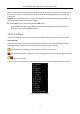
Table Of Contents
- Chapter1 Panels Description
- Chapter 2 Installation and Connections
- Chapter 3 Menu Operation
- 3.1 Menu Structure
- 3.2 Startup and Shutdown
- 3.3 Activating Your Device
- 3.4 Using the Unlock Pattern for Login
- 3.5 Login and Logout
- 3.6 Using the Setup Wizard
- 3.7 Configuring Signal Input Channel
- 3.8 Network Settings
- 3.9 General Settings
- 3.10 Adding IP Cameras
- 3.11 Configuring Custom Protocols
- 3.12 Live View
- 3.13 ATM Settings
- 3.14 Smart ATM Settings
- 3.15 Recording Settings
- 3.16 Playback
- Chapter 4 Accessing by Web Browser

ATM Digital Video Recorder Quick Start Guide
29
Before customizing the protocol for the network camera, you have to contact the manufacturer of
the network camera to consult the URL (uniform resource locator) for getting main stream and
sub-stream.
Example: The format of the URL is: [Type]://[IP Address of the network camera]:[Port]/[Path]. E.g.,
rtsp://192.168.1.55:554/ch1/main/av_stream.
Step 3 Click Apply to save the settings and click OK to exit.
After added successfully, the custom protocol will be displayed in the drop-down list of
protocol on the Custom Adding interface.
3.12 Live View
Icons are provided on screen in Live View mode to indicate camera status. These icons include:
Live View Icons
In the live view mode, there are icons at the upper-right corner of the screen for each channel,
showing the status of the record and alarm in the channel for quick reference.
Alarm (video loss, tampering, motion detection, VCA or sensor alarm)
Record (manual record, continuous record, motion detection, VCA or alarm triggered record)
Alarm and Record
In the live view mode, use the mouse to right-click on the window to access the following menu.
Figure 3-26 Right-Click Menu