
Quick Start Guide


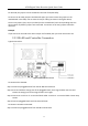
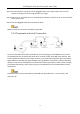


Table Of Contents
- Chapter1 Panels Description
- Chapter 2 Installation and Connections
- Chapter 3 Menu Operation
- 3.1 Menu Structure
- 3.2 Startup and Shutdown
- 3.3 Activating Your Device
- 3.4 Using the Unlock Pattern for Login
- 3.5 Login and Logout
- 3.6 Using the Setup Wizard
- 3.7 Configuring Signal Input Channel
- 3.8 Network Settings
- 3.9 General Settings
- 3.10 Adding IP Cameras
- 3.11 Configuring Custom Protocols
- 3.12 Live View
- 3.13 ATM Settings
- 3.14 Smart ATM Settings
- 3.15 Recording Settings
- 3.16 Playback
- Chapter 4 Accessing by Web Browser

ATM Digital Video Recorder Quick Start Guide
13
For DC load, the jumpers can be used within the limit of 12V/1A safely.
To connect an AC load, jumpers should be left open (you must remove the jumper on the
motherboard in the DVR). Use an external relay for safety (as shown in the figure above).
There are 4 jumpers (JP1, JP2, JP3, and JP4) on the motherboard, each corresponding with one
alarm output. By default, jumpers are connected. To connect an AC load, jumpers should be
removed.
Example:
If you connect an AC load to the alarm output 3 of the DVR, then you must remove the JP3.
2.3.3 RS-485 and Controller Connection
Typical Connection:
Figure 2-9 RS-485 Connection
To connect PTZ to the DVR:
Step 1 Disconnect pluggable block from the RS-485 terminal block.
Step 2 Press and hold the orange part of the pluggable block; insert signal cables into slots and
release the orange part. Ensure signal cables are in tight.
Step 3 Connect A+ on PTZ to T+ on terminal block and B- on PTZ to T- on terminal block. Fasten stop
screws.
Step 4 Connect pluggable block back into terminal block.
To connect a controller to the DVR:
Step 1 Disconnect pluggable block from the KB terminal block.