
Quick Start Guide


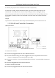
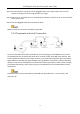


Table Of Contents
- Chapter1 Panels Description
- Chapter 2 Installation and Connections
- Chapter 3 Menu Operation
- 3.1 Menu Structure
- 3.2 Startup and Shutdown
- 3.3 Activating Your Device
- 3.4 Using the Unlock Pattern for Login
- 3.5 Login and Logout
- 3.6 Using the Setup Wizard
- 3.7 Configuring Signal Input Channel
- 3.8 Network Settings
- 3.9 General Settings
- 3.10 Adding IP Cameras
- 3.11 Configuring Custom Protocols
- 3.12 Live View
- 3.13 ATM Settings
- 3.14 Smart ATM Settings
- 3.15 Recording Settings
- 3.16 Playback
- Chapter 4 Accessing by Web Browser

ATM Digital Video Recorder Quick Start Guide
12
2.3 Peripheral Connections
2.3.1 Wiring of Alarm Input
The alarm input is an open/closed relay. To connect the alarm input to the device, use the
following diagram.
If the alarm input is not an open/close relay, please connect an external relay between the alarm
input and the device.
Figure 2-6 Wiring of Alarm Input
2.3.2 Wiring of Alarm Output
To connect to an alarm output (AC or DC load), use the following diagram:
Figure 2-7 DC Load Connection Diagram
Figure 2-8 AC Load Connection Diagram