
Quick Start Guide


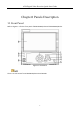

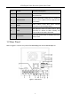

Table Of Contents
- Chapter1 Panels Description
- Chapter 2 Installation and Connections
- Chapter 3 Menu Operation
- 3.1 Menu Structure
- 3.2 Startup and Shutdown
- 3.3 Activating Your Device
- 3.4 Using the Unlock Pattern for Login
- 3.5 Login and Logout
- 3.6 Using the Setup Wizard
- 3.7 Configuring Signal Input Channel
- 3.8 Network Settings
- 3.9 General Settings
- 3.10 Adding IP Cameras
- 3.11 Configuring Custom Protocols
- 3.12 Live View
- 3.13 ATM Settings
- 3.14 Smart ATM Settings
- 3.15 Recording Settings
- 3.16 Playback
- Chapter 4 Accessing by Web Browser

ATM Digital Video Recorder Quick Start Guide
9
Table 1-2 Description of Rear Panel
No.
Item
Description
1
VIDEO IN
BNC connector for analog video input.
2
AUDIO IN
BNC connector for audio input.
3
LINE IN
BNC connector for two-way audio.
4
AUDIO OUT
BNC connector for audio output.
5
HDMI
HDMI video output connector.
6
VGA
DB15 connector for VGA output. Display local video
output and menu.
7
RS-232
Interface
Connector for RS-232 devices.
8
LAN Interface
RJ45 10M/100M/1000M Ethernet interface.
9
DC Output
12 VDC output.
10
ALARM IN
Connector for alarm input.
11
RS-485
Interface
Connector for RS-485 devices.
12
ALARM OUT
Connector for alarm output.
13
VIDEO OUT
BNC connector for analog video output.
14
GND
Ground
15
Power Switch
Switch for turning on/off the device.
16
Power Supply
100 to 240 VAC power supply.