
Quick Start Guide

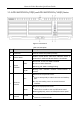


Table Of Contents

Network Video Recorder Quick Start Guide
17
1.2.4 iDS-7700NXI-I4/(16P)/16S(B) Series
Figure 1-11 iDS-7700NXI-I4/16S(B) Series Rear Panel
Figure 1-12 iDS-7700NXI-I4/16P/16S(B) Series Rear Panel
Table 1-9 Panel Description
9
Controller Port
D+, D- pin connects to Ta, Tb pin of controller. For
cascading devices, the first NVR’s D+, D- pin should
be connected with the D+, D- pin of the next NVR.
ALARM IN
Connector for alarm input.
ALARM OUT
Connector for alarm output.
10
100 to 240 VAC
100 to 240 VAC power supply.
11
Power Switch
Switch for turning on/off the device.
12
GROUND
Ground (needs to be connected when NVR starts
up).
No.
Name
Description
1
LAN Interface
1 network interface provided by
iDS-7700NXI-I4/16P/16S(B) series, and 2
network interfaces by iDS-7700NXI-I4/16S(B)
series.
2
AUDIO OUT
RCA connector for audio output.
3
LINE IN
RCA connector for audio input.
4
HDMI
HDMI video output connector.