
User Manual
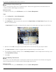
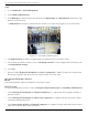
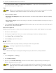
Table Of Contents
- Legal Information
- About this Manual
- Trademarks
- Disclaimer
- Symbol Conventions
- Safety Instruction
- Contents
- Chapter 1 System Requirements
- Chapter 2 Device Activation and Accessing
- Illegal Login Lock
- Chapter 3 Live View
- 3
- 3.1 Live View Parameters
- 3.1.1 Enable and Disable Live View
- 3.1.2 Adjust Aspect Ratio
- 3.1.3 Live View Stream Type
- 3.1.4 Select Third-Party Plug-in
- 3.1.5 Window Division
- 3.1.6 Light
- 3.1.7 Count Pixel
- 3.1.8 Start Digital Zoom
- 3.1.9 Auxiliary Focus
- 3.1.10 Lens Initialization
- 3.1.11 Quick Set Live View
- 3.1.12 Lens Parameters Adjustment
- 3.1.13 Conduct 3D Positioning
- 3.2 Set Transmission Parameters
- 3.3 Set Smooth Streaming
- Chapter 4 Video and Audio
- Chapter 5 Video Recording and Picture Capture
- Chapter 6 Events and Alarms
- 6
- 6.1 Basic Event
- 6.2 Smart Event
- 6.2.1 Detect Audio Exception
- 6.2.2 Set Defocus Detection
- 6.2.3 Detect Scene Change
- 6.2.4 Set Face Detection
- 6.2.5 Set Video Loss
- 6.2.6 Set Intrusion Detection
- 6.2.7 Set Line Crossing Detection
- 6.2.8 Set Region Entrance Detection
- 6.2.9 Set Region Exiting Detection
- 6.2.10 Set Unattended Baggage Detection
- 6.2.11 Set Object Removal Detection
- 6.2.12 Draw Area
- 6.2.13 Set Size Filter
- Chapter 7 Network Settings
- Chapter 8 Arming Schedule and Alarm Linkage
- Chapter 9 System and Security
- 9
- 9.1 View Device Information
- 9.2 Search and Manage Log
- 9.3 Simultaneous Login
- 9.4 Import and Export Configuration File
- 9.5 Export Diagnose Information
- 9.6 Reboot
- 9.7 Restore and Default
- 9.8 Upgrade
- 9.9 View Open Source Software License
- 9.10 Time and Date
- 9.11 Set RS-485
- 9.12 Set RS-232
- 9.13 External Device
- 9.14 Security
- 9.15 Certificate Management
- 9.16 User and Account
- Chapter 10 Allocate VCA Resource
- Chapter 11 Open Platform
- Chapter 12 Set EPTZ
- Chapter 13 Smart Display
- Appendix A: Device Command
- Appendix B: Device Communication Matrix

iDS-2CD7xxG0-xxxxx Network Bullet Camera User Manual
UM iDS-2CD7xxG0-xxxxx 021021NA 93
• Max. Pupil Distance: The max. pupil distance refers to the maximum square size composed by the
area between two pupils, and it is the basic standard for a camera to identify a target.
5. Click to draw the detection area. Draw an area by left-clicking end-points in the live view window,
and right-clicking to finish the area drawing.
6. Click to draw the detection line. The arrow shows entering direction, you can click to change the
direction.
• If the target crosses the counting area along the entering direction and crosses the detection line,
then it is counted as the entering number.
• If the target crosses the counting area along the exiting direction and crosses the detection line,
then it is counted as the exiting number.
7. Click and to draw region A and B. Make sure the two areas don't overlap. You can click to
change the direction.
• If the target enters from A region to B region, then it is counted as the entering number.
• If the target enters from B region to A region, then it is counted as the exiting number.
8. Set arming schedule. See Set Arming Schedule.
9. Set linkage method. See Linkage Method Settings.
Overlay and Capture
Choose to configure capture parameters and the information you want to display on stream and picture.
• Display VCA info. on Stream: Display smart information on stream, including the target and rules
information.
• Display Target info. on Alarm Picture: Overlay the alarm picture with target information.
• Target Picture Settings: Custom, Head Shot, Half-Body Shot, and Full-Body Shot are selectable.
If you select Custom, you can customize width, head height and body height as required.
You can check Fixed Value to set the picture height.
• Background Picture Settings: Comparing to target picture, background picture is the scene image
offers extra environmental information. You can set the background picture quality and resolution. If
the background image needs to be uploaded to surveillance center, check Background Upload.
• People Counting Overlay: Select flow overlay type. Select the daily reset time. Click Manual Reset if
you want to reset right now.
• Camera: You can set Device No. and Camera Info. for the camera, which can be overlaid on captured
picture.
• Text Overlay: You can check desired items and adjust their order to display on captured pictures by
. The content of Device No. and Camera Info should be on the same page.