
User Manual
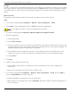

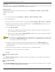
Table Of Contents
- Legal Information
- About this Manual
- Trademarks
- Disclaimer
- Symbol Conventions
- Safety Instruction
- Contents
- Chapter 1 System Requirements
- Chapter 2 Device Activation and Accessing
- Illegal Login Lock
- Chapter 3 Live View
- 3
- 3.1 Live View Parameters
- 3.1.1 Enable and Disable Live View
- 3.1.2 Adjust Aspect Ratio
- 3.1.3 Live View Stream Type
- 3.1.4 Select Third-Party Plug-in
- 3.1.5 Window Division
- 3.1.6 Light
- 3.1.7 Count Pixel
- 3.1.8 Start Digital Zoom
- 3.1.9 Auxiliary Focus
- 3.1.10 Lens Initialization
- 3.1.11 Quick Set Live View
- 3.1.12 Lens Parameters Adjustment
- 3.1.13 Conduct 3D Positioning
- 3.2 Set Transmission Parameters
- 3.3 Set Smooth Streaming
- Chapter 4 Video and Audio
- Chapter 5 Video Recording and Picture Capture
- Chapter 6 Events and Alarms
- 6
- 6.1 Basic Event
- 6.2 Smart Event
- 6.2.1 Detect Audio Exception
- 6.2.2 Set Defocus Detection
- 6.2.3 Detect Scene Change
- 6.2.4 Set Face Detection
- 6.2.5 Set Video Loss
- 6.2.6 Set Intrusion Detection
- 6.2.7 Set Line Crossing Detection
- 6.2.8 Set Region Entrance Detection
- 6.2.9 Set Region Exiting Detection
- 6.2.10 Set Unattended Baggage Detection
- 6.2.11 Set Object Removal Detection
- 6.2.12 Draw Area
- 6.2.13 Set Size Filter
- Chapter 7 Network Settings
- Chapter 8 Arming Schedule and Alarm Linkage
- Chapter 9 System and Security
- 9
- 9.1 View Device Information
- 9.2 Search and Manage Log
- 9.3 Simultaneous Login
- 9.4 Import and Export Configuration File
- 9.5 Export Diagnose Information
- 9.6 Reboot
- 9.7 Restore and Default
- 9.8 Upgrade
- 9.9 View Open Source Software License
- 9.10 Time and Date
- 9.11 Set RS-485
- 9.12 Set RS-232
- 9.13 External Device
- 9.14 Security
- 9.15 Certificate Management
- 9.16 User and Account
- Chapter 10 Allocate VCA Resource
- Chapter 11 Open Platform
- Chapter 12 Set EPTZ
- Chapter 13 Smart Display
- Appendix A: Device Command
- Appendix B: Device Communication Matrix

iDS-2CD7xxG0-xxxxx Network Bullet Camera User Manual
UM iDS-2CD7xxG0-xxxxx 021021NA 68
Chapter 8 Arming Schedule and Alarm Linkage
Arming schedule is a customized time period in which the device performs certain tasks. Alarm linkage is
the response to the detected certain incident or target during the scheduled time.
Set Arming Schedule
Set the valid time of the device tasks.
Steps
1. Click Arming Schedule.
2. Drag the time bar to draw desired valid time.
Up to eight periods can be configured for one day.
3. Adjust the time period.
• Click on the selected time period, and enter the desired value. Click Save.
• Click on the selected time period. Drag the both ends to adjust the time period.
• Click on the selected time period, and drag it on the time bar.
4. Optional: Click Copy to... to copy the same settings to other days.
5. Click Save.
Linkage Method Settings
You can enable the linkage functions when an event or alarm occurs.
Trigger Alarm Output
If the device has been connected to an alarm output device, and the alarm output No. has been configured,
the device sends alarm information to the connected alarm output device when an alarm is triggered.
Steps
1. Go to Configuration → Event → Basic Event → Alarm Output.
2. Set alarm output parameters.
• Automatic Alarm: For the information about the configuration, see Automatic Alarm.
• Manual Alarm: For the information about the configuration, see Manual Alarm.
3. Click Save.
Manual Alarm
You can trigger an alarm output manually.