
User Manual
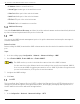
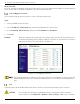
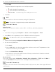
Table Of Contents
- Legal Information
- About this Manual
- Trademarks
- Disclaimer
- Symbol Conventions
- Safety Instruction
- Contents
- Chapter 1 System Requirements
- Chapter 2 Device Activation and Accessing
- Illegal Login Lock
- Chapter 3 Live View
- 3
- 3.1 Live View Parameters
- 3.1.1 Enable and Disable Live View
- 3.1.2 Adjust Aspect Ratio
- 3.1.3 Live View Stream Type
- 3.1.4 Select Third-Party Plug-in
- 3.1.5 Window Division
- 3.1.6 Light
- 3.1.7 Count Pixel
- 3.1.8 Start Digital Zoom
- 3.1.9 Auxiliary Focus
- 3.1.10 Lens Initialization
- 3.1.11 Quick Set Live View
- 3.1.12 Lens Parameters Adjustment
- 3.1.13 Conduct 3D Positioning
- 3.2 Set Transmission Parameters
- 3.3 Set Smooth Streaming
- Chapter 4 Video and Audio
- Chapter 5 Video Recording and Picture Capture
- Chapter 6 Events and Alarms
- 6
- 6.1 Basic Event
- 6.2 Smart Event
- 6.2.1 Detect Audio Exception
- 6.2.2 Set Defocus Detection
- 6.2.3 Detect Scene Change
- 6.2.4 Set Face Detection
- 6.2.5 Set Video Loss
- 6.2.6 Set Intrusion Detection
- 6.2.7 Set Line Crossing Detection
- 6.2.8 Set Region Entrance Detection
- 6.2.9 Set Region Exiting Detection
- 6.2.10 Set Unattended Baggage Detection
- 6.2.11 Set Object Removal Detection
- 6.2.12 Draw Area
- 6.2.13 Set Size Filter
- Chapter 7 Network Settings
- Chapter 8 Arming Schedule and Alarm Linkage
- Chapter 9 System and Security
- 9
- 9.1 View Device Information
- 9.2 Search and Manage Log
- 9.3 Simultaneous Login
- 9.4 Import and Export Configuration File
- 9.5 Export Diagnose Information
- 9.6 Reboot
- 9.7 Restore and Default
- 9.8 Upgrade
- 9.9 View Open Source Software License
- 9.10 Time and Date
- 9.11 Set RS-485
- 9.12 Set RS-232
- 9.13 External Device
- 9.14 Security
- 9.15 Certificate Management
- 9.16 User and Account
- Chapter 10 Allocate VCA Resource
- Chapter 11 Open Platform
- Chapter 12 Set EPTZ
- Chapter 13 Smart Display
- Appendix A: Device Command
- Appendix B: Device Communication Matrix

iDS-2CD7xxG0-xxxxx Network Bullet Camera User Manual
UM iDS-2CD7xxG0-xxxxx 021021NA 56
What To Do Next
Go to the router port mapping settings interface and set the port number and IP address to be the same as
those on the device. For more information, see the router user manual.
Set Port Mapping on Router
The following settings are for a specific router. Settings vary by router.
Steps
1. Select the WAN Connection Type.
2. Set the IP Address, Subnet Mask and other network parameters of the router.
3. Go to Forwarding → Virtual Servers, and input the Port Number and IP Address.
4. Click Save.
Example: When the cameras are connected to the same router, you can configure the ports of
a camera as 80, 8000, and 554 with IP address 192.168.1.23, and the ports of another
camera as 81, 8001, 555, 8201 with IP 192.168.1.24.
Figure 7-1 Port Mapping on Router
The network camera port cannot conflict with other ports. For example, for some routers the
Web management port is 80. Change the camera port if it is the same as the management
port.
Port
The device port can be modified when the device cannot access the network due to port conflicts.
CAUTION! Do not modify the default port parameters at will, otherwise the device may be
inaccessible. Go to Configuration → Network → Basic Settings → Port for port settings.